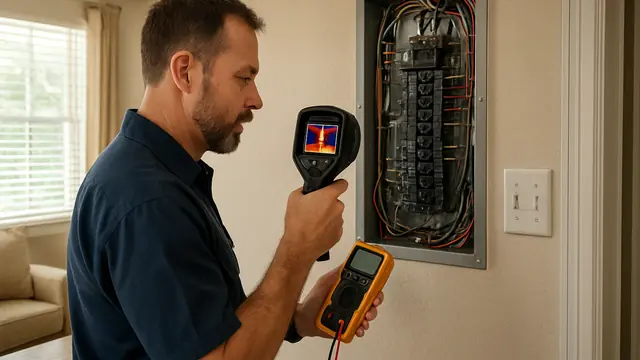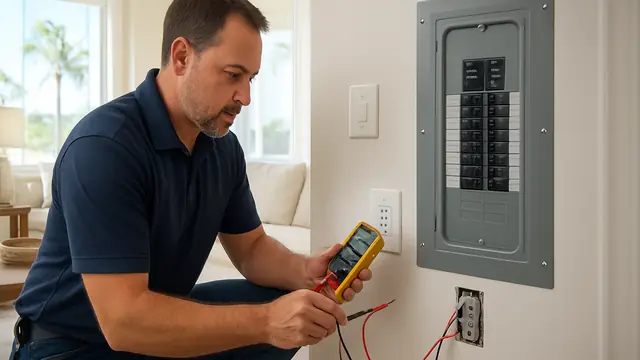
Do not remove an electrical panel cover, touch exposed conductors, bypass protection, or repeatedly reset a fault. Keep clear of smoke, sparks, burning odors, hot equipment, standing water near electricity, and downed lines, then call qualified help.
1. Define the Renovation Around Household Workflows
Start with what the kitchen and laundry room must support, not a shopping list of outlets and upgrades. The project brief should identify who uses each room, which tasks overlap, and what prevents those tasks from working well today. Homeowners can observe ordinary use and accessible equipment; electrical design, concealed investigation, installation, and repairs belong to licensed professionals. At this stage, define the results you need while leaving the technical solutions open.
Classify the work separately for each room. A cosmetic refresh retains the arrangement and equipment while changing finishes. An appliance replacement changes equipment without necessarily changing the room layout; its electrical implications are addressed through the appliance register in Chapter 2. A reconfiguration moves appliances, cabinetry, work zones, or travel paths. Mixed projects should say so explicitly. This distinction helps the team understand whether it is preserving an arrangement, accommodating new equipment, or redesigning how people use the space.
Observe a representative stretch of household activity, including busy periods rather than only quiet weekday routines. For cooking and food preparation, record how many people participate, where groceries land, where ingredients are prepared, and which powered appliances are used together. Distinguish everyday requirements from occasional demands: hosting a large meal may justify flexible preparation space without making a permanent second cooking station essential. Describe simultaneous activities, not estimated electrical loads; circuit planning belongs in Chapter 7.
Track cleanup as a separate workflow. Where do dirty dishes wait, who loads the dishwasher, and where are bulky pans washed and dried? Note whether cleanup displaces meal preparation or an open appliance door interrupts a frequently used route. Identify the actual source of the difficulty before labeling it an electrical shortcoming. Insufficient landing space, awkward storage, or competing traffic may require a layout decision rather than additional power.
For laundry, follow the complete path from incoming baskets through sorting, washing, drying, folding, hanging, and returning items to storage. Record bulky loads, the number of loads commonly handled in one session, and where ironing or other garment care occurs. If the room also provides access to an exterior door or household storage, note when those uses conflict. Separate a need for working space from a habit caused by the present layout: folding elsewhere may be a preference, or it may reflect the lack of a usable surface.
Make a simple activity sketch showing doors, windows, existing cabinets, appliance fronts, and normal travel paths. Mark where people set down groceries or baskets, where doors and drawers interrupt movement, and where two users need to pass. Include accessible measurements where useful, without moving heavy appliances or entering concealed spaces. Label activities and conflicts rather than choosing receptacle, connection, or switch locations; those decisions follow in the room-layout chapters.
Include users with different reach, mobility, and strength needs. Record whether a seated person can approach the intended task area, whether deep surfaces put everyday items out of reach, and where bending or carrying makes a task difficult. Assess space while it is in use, not merely when everything is closed and empty. More seating can reduce preparation access; a larger folding counter can narrow a passage. Name the activity that takes priority when both cannot comfortably occupy the same space.
Rank shortcomings by consequence, frequency, and who is affected. Essential outcomes should support recurring tasks, necessary access, or evaluation of an observed concern. Write outcomes that can later be checked through ordinary use, such as keeping the primary passage usable during laundry loading. Keep preferred solutions separate: an added station is not automatically essential simply because the activity is. Optional alternates should have a clear benefit and remain removable without undermining the core project.
Panama City's heat and humidity matter when they affect these rooms in practice. Record when discomfort or dampness occurs and which activities it disrupts, rather than assuming more electrical equipment will solve it. Seasonal occupancy belongs in the brief when it changes the number of users, their familiarity with the rooms, or the duration of unattended periods. Local conditions alone are not a reason to expand the project into unrelated whole-home work.
- Define the boundary: rooms included, renovation category for each, and equipment or features intended to remain.
- List users, recurring tasks, likely overlaps, and access needs; attach the activity sketch.
- Rank essential outcomes and state how the household will recognize that each has been achieved.
- Separate optional alternates from essentials and identify unresolved tradeoffs before fixing locations.
- State exclusions. Broader work should have a documented connection to the room project and owner authorization; necessary supporting work should not be confused with discretionary modernization.
2. Build an Appliance Specification and Purchasing Register
Build one appliance register that purchasing, cabinetry, and electrical planning can reference. Include retained appliances as well as proposed purchases, and assign each a stable identifier such as K-01 or L-02. Keep that identifier when a selection changes so references on drawings remain traceable. The register owns product facts and selection status; Chapter 7 addresses circuit design, and Chapter 13 coordinates project approvals and construction milestones.
Record the complete manufacturer model number, including suffixes. A product-family name or advertised width can cover models with different electrical requirements and installation arrangements. Compare the supplier’s quoted model with the model covered by the manufacturer’s documents. For retained equipment, add the serial number if safely visible; it may help identify the applicable instructions. Leave that field blank for an unpurchased appliance rather than copying a showroom unit’s serial number.
Use the fields below consistently. Attach units to every numerical rating and identify the source page. Write “not confirmed” where information is missing. If a manual covers several models, identify the row or section that applies to the selected unit rather than copying the family’s highest or lowest rating.
Electrical input is the power an appliance takes from its supply, not its useful cooking output. A microwave’s advertised cooking wattage cannot substitute for its electrical input rating. Likewise, individual cooktop element and boost ratings are not a homeowner calculation of the appliance’s required supply. Preserve the manufacturer’s appliance-level ratings and any conditions attached to them. Volts, amperes, watts, and kilowatts describe different electrical quantities; kilowatt-hours measure energy consumed over time. Annual energy-use estimates, efficiency labels, and marketing terms do not establish circuit requirements. Where instructions distinguish supply voltages or configurations, retain each applicable condition rather than selecting a convenient value.
Gather receipts and order acknowledgments to establish what was purchased, then obtain model-specific installation instructions, specification sheets, and accessory instructions from the manufacturer. Confirm that documents cover the intended market. Retailer summaries are useful for shopping but should not settle technical discrepancies. Photograph existing labels only from a normal, safely accessible position, including an ordinarily accessible door opening. Do not move heavy appliances, remove covers, or reach behind equipment to fill a missing field; flag it for professional confirmation.
Keep selection, technical review, and purchasing status in separate fields. “Preferred,” “review pending,” and “ordered” describe different conditions and may apply simultaneously. Give separate candidates distinct entries when comparing a combined appliance with separate units, and mark those entries as mutually exclusive alternatives. Link optional accessories to the parent appliance and state whether each is included, excluded, or undecided. An accessory that needs its own power connection should remain visible as a separate planning item, not disappear into a package description.
Before an order becomes difficult to change, send unresolved model-specific ratings, supply instructions, permitted connection methods, and required connection components to the licensed electrician. Route dimensional and connection-space questions to the cabinet designer and appropriate licensed installation professional. Record the outcome against the exact model and configuration; use Chapter 13’s milestone process for the purchase release. Conflicting manufacturer documents remain an open issue until model-specific clarification resolves them.
Treat a supplier substitution as a replacement selection, not an administrative correction. Retain the superseded entry and identify changes to ratings, connection method, dimensions, accessories, and document applicability. Route those differences to the affected reviewers. Track document revision identifiers separately from retrieval dates: downloading a manual today does not make it a newer edition. Release the register with a version identifier, make superseded versions clearly inactive, and link the current version to the corresponding order and drawings.
- Identity: stable identifier, room and function, manufacturer, complete model number, retained/new/alternate status, supplier’s quoted model, and serial number when applicable.
- Sources: installation manual, specification sheet, and accessory instructions; filenames or links, revision identifiers, retrieval dates, and relevant pages. Preserve unresolved conflicts rather than silently choosing one source.
- Electrical data: manufacturer-stated voltage, frequency, phase where specified, input amperes or watts, and circuit or overcurrent-protection instructions. Distinguish mandatory requirements from recommendations.
- Connection and accessories: permitted cord-and-plug or hardwired arrangement, specified plug or connection components, included versus separately purchased parts, accessory model numbers, compatibility, and any separate power requirement.
- Physical interfaces: installation dimensions, required clearances, and documented connection zones or connection-space allowances, not merely the appliance’s advertised width.
- Decision and purchase controls: selected configuration, mutually exclusive alternatives, open questions and responsible reviewer, review date and outcome, order status, supplier substitution restrictions, and actual cancellation or return deadlines and terms.
3. Plan Power for Ranges, Cooktops, Ovens, and Ventilation
Choose the cooking arrangement using the models in Chapter 2’s appliance register. A single range, a separate cooktop and wall oven, and a multi-appliance cooking suite create different connection locations and cabinet constraints. Resolve those cooking-zone differences here; Chapter 7 covers circuit design, and Chapter 13 sets the project approval milestones.
A freestanding range combines surface cooking and an oven within one appliance, usually concentrating the electrical connection near its installed position. The manufacturer’s permitted connection zone can be a small recess rather than the whole space behind the range. Connection hardware must fit within that zone without interfering with the chassis or anti-tip provisions. This is especially consequential when a replacement must sit flush with existing counters: cabinet width alone does not establish the required rear clearance.
Separate cooktops and wall ovens create distinct connection points, even when the oven is directly beneath the cooktop. For an under-cooktop oven, check that the manufacturers permit the combination and that the cooktop’s underside, connection enclosure, and cooling clearances leave the required oven space. A tall-cabinet oven removes that particular conflict but introduces a different connection location and removal path. The electrician determines the permitted supply arrangement; the former range connection does not dictate how the new pair must be supplied.
An additional oven, warming drawer, or built-in specialty cooking appliance introduces another connection and may constrain the installation above or below it. Identify which appliances need to operate together, such as two ovens and a cooktop during meal preparation, and pass that use pattern to the Chapter 7 design. Occasional use does not remove an appliance’s installation requirements. Compare the added cooking capability with the cabinet space, cooling provisions, and servicing complexity it consumes.
For a gas-to-electric or induction conversion, the existing gas appliance’s electrical connection may serve only ignition and auxiliary functions. The electrician must assess the replacement’s supply needs and whether a suitable supply can reach the cooking location, escalating capacity questions through Chapter 7. The conversion also has a physical dependency: any remaining gas piping must not obstruct the new appliance’s connection recess or installed depth. A licensed gas professional handles disconnection, capping, relocation, and other gas-system changes; coordinate that work with removal and installation.
Induction boost claims describe cooking performance under defined conditions, not necessarily power available to every cooking zone at once. Some models share power between zones, so boosting one can limit another. Ask which zones share power and what happens when several large pans are used simultaneously. Manufacturer-supported power-limiting configurations may also reduce simultaneous performance. Those tradeoffs matter when choosing the model, while the electrician uses its electrical input ratings and installation instructions, not a sum of advertised burner outputs, to establish supply requirements.
Wall-oven cabinetry needs a deliberate connection and removal sequence. A junction box behind the oven can compete with chassis depth; an adjacent-cabinet location may conflict with drawers or require a permitted route for the appliance lead. The location must suit the supplied lead and manufacturer instructions. For stacked ovens and warming drawers, resolve whether one appliance must be removed to service another and whether cabinet partitions provide the specified support and clearances. Do not trade away required cooling space to conceal connections.
Ventilation choices determine more than the hood’s power location. An integrated blower keeps most equipment together, whereas a remote blower introduces separated components with model-specific power and control interfaces. Establish hood, blower, and control compatibility before concealing their routes. Decorative chimney covers can crowd ductwork and electrical connection boxes; remote blowers need an appropriate service-access arrangement at their own location. The electrician coordinates electrical interfaces, including any required interlock, with the licensed trades responsible for airflow, ducts, discharge, and makeup air. Induction removes combustion at the cooktop but not cooking emissions.
- Before cabinet fabrication: settle the range versus separate-appliance layout, permitted under-cooktop or stacked combinations, connection recesses, cabinet partitions, and appliance-removal sequence.
- Before fixing ventilation enclosures: resolve hood and blower selection, power and control routes, duct conflicts, and service access for separated components.
- Before appliance delivery: resolve any gas-piping obstruction and confirm that the selected cooking equipment’s connection zones remain compatible with the completed cabinet layout.
- If a manufacturer-supported power limit is part of the design, decide whether its simultaneous-cooking restrictions are acceptable before committing to that model.
4. Give Refrigeration and Specialty Food Storage Their Own Plan
Plan for the refrigerated storage the household actually intends to use: the main refrigerator, a separate freezer, beverage or wine coolers, refrigerated drawers, and any retained units being relocated. Separate committed equipment from possible additions. Decide what each unit will hold before choosing its location; a beverage cooler’s temperature range may not suit perishable food, and a wine cabinet is not interchangeable with a refrigerator. Consider whether frequently accessed drinks should be separate from longer-term food storage, and whether an extra unit provides useful capacity or merely duplicates storage.
Using the appliance register in Chapter 2, have the electrician check each unit’s supply requirements and distinguish manufacturer requirements from recommendations for an individual circuit. Compressor starting demand and any specified circuit restrictions deserve attention; annual energy consumption does not describe those demands. Leave circuit assignments and required protection to the strategy in Chapter 7. The refrigeration-specific decision is which units need to operate continuously and how much stored food would be affected if several units lost power together, not an assumption that every refrigerator needs the same electrical arrangement.
Product format changes the usable space around the appliance. Built-in models typically specify utility zones, attachment details, and a service-removal path. Counter-depth describes cabinet-depth relationships, not flush doors or extra room for connections. Door hinges and handles may still project, and doors may need to open beyond a right angle to remove bins. Drawer-style units need clearance for full drawer extension, adjacent handles, and anyone standing at nearby counters. Freestanding equipment should not be treated as built-in simply because it fits inside an opening; its enclosure and ventilation instructions govern that choice.
Check connection space with the actual plug, cord, and any water fittings included, rather than using the appliance case dimensions alone. A receptacle behind the wrong part of the refrigerator can prevent it from reaching its intended position or put pressure on the plug. An adjacent-cabinet connection is useful only if the manufacturer permits the arrangement and the cord reaches through an approved route without tension or pinching. Extension cords and adapters are not a solution to a mismatched layout. The model’s connection zone should guide placement, rather than a generic refrigerator outlet height.
For water-fed equipment, the plumber’s connection and shutoff must coexist with the electrical connection, rear appliance components, and anti-tip provisions. Tubing needs an arrangement that supports the prescribed installation and withdrawal procedure without kinking or becoming trapped. Anti-tip hardware can also occupy space assumed available for utility routes. These are specific dependencies for the electrician, plumber, and cabinet installer to resolve together: where the appliance rests, how it is secured, and how professionals can withdraw it for service. Homeowners should not pull out heavy units to investigate hidden connections.
Ventilation can rule out a location even when the electrical supply is suitable. Confirm whether the selected model releases heat through a front grille or requires other clearances; decorative toe-kicks, trim, and nearby storage must not obstruct the specified airflow. Cabinet depth and tight side panels can change whether an otherwise suitable opening works. Also check the permitted ambient-temperature range, especially for a freezer proposed for an unconditioned space in Panama City’s heat. A new circuit cannot correct blocked airflow, an unsuitable room temperature, or an appliance fault. Poor cooling, persistent condensation, or unusual cycling calls for assessment of the appliance and its surroundings, not an automatic electrical upgrade.
For unattended storage, compare alarms by what they detect. Door-open alerts address an incompletely closed door; high-temperature alerts can identify a cooling problem but may include a delay. Power-loss alerts depend on a means of detecting and reporting the interruption after appliance power disappears. Check threshold options, alarm delays, and whether settings and notifications resume after power returns. An independent temperature monitor may cover equipment without built-in alerts, provided its sensor is suitable for the storage temperature and its batteries are maintained.
Remote monitoring is valuable only when an alert can reach someone who can respond. During seasonal absences or storm outages, the appliance, router, and internet service may fail together. Look for loss-of-contact notifications and understand whether stored readings become available only after reconnection. Battery-backed sensing does not necessarily preserve communication, and neither feature keeps food cold. Temperature history can inform a response, but an alarm’s silence, or a restored normal reading, does not establish that food remained safe.
- Does each unit’s specified temperature range match its intended contents?
- Can doors, bins, and refrigerated drawers open or be removed without striking adjacent cabinetry or handles?
- Does the model-specific connection space accommodate the plug, water fittings, and anti-tip provisions while preserving ventilation?
- Who receives unattended-storage alerts, who can respond locally, and how will loss of communication be recognized?
5. Coordinate Dishwasher, Disposal, and Sink-Cabinet Power
Plan the sink cabinet around the assembled cleanup zone: sink bowl, disposer, drain trap, dishwasher connections, supply valves, and any treatment equipment. Then allocate space for pullout bins and supplies. Sink depth and drain position affect the space available below, so a cabinet’s exterior dimensions alone cannot establish whether everything will fit. Use the appliance register from Chapter 2 for equipment requirements and Chapter 7 for circuit decisions; this chapter resolves how those choices work together beneath the sink.
For the dishwasher and disposer, have the electrician use the registered specifications to decide whether existing connections can remain, including compatibility with the selected connection kits and controls. The distinctive question here is how each appliance’s supply and disconnect arrangement fits the cabinet layout. A cord-and-plug connection needs an approved cord arrangement and appropriate access to the plug; permanent wiring needs an appropriate disconnecting means and access to its connection enclosure. Neither arrangement should be selected solely to avoid relocating an inconvenient receptacle.
Distinguish the dishwasher’s own connection compartment from its supply location. Follow the selected model’s instructions and applicable requirements rather than assuming a receptacle belongs behind the machine. A protruding plug or connection box can consume installation depth, while routing into an adjacent cabinet requires suitable openings and protection against abrasion or pinching. Coordinate the electrical route with the dishwasher’s water and drain routes so cabinet hardware cannot crush any of them and appliance removal does not strain connections.
Lay out the sink cabinet with equipment dimensions and service movements, not just footprints. A filter housing may need room below it for cartridge removal; a treatment tank can block a valve or electrical connection; and a pullout-bin frame can strike a plug even when the bin clears the disposer. Include the disposer body, drain trap, slides, and shelf supports. Locate electrical components away from avoidable leakage exposure while meeting applicable requirements. Simply mounting them as high as possible can put them behind the sink bowl or make access worse. Reserve storage space that keeps bottles and loose supplies out of connection and moving-hardware areas.
Compare disposer controls by reach, operating effort, cleaning access, and installation dependencies. A wall switch offers familiar operation without adding a countertop penetration, but its position may require reaching across the sink or conflict with backsplash features. Identify it clearly enough that users do not confuse it with lighting controls. A countertop air button can put the control closer to the user; pressing it sends a pneumatic signal to a separate electrical switching unit. The button still needs a compatible system, an approved mounting opening, tubing space, and room for the switching unit below. Check whether faucet handles, soap dispensers, or drying racks would obstruct operation or cleaning around the button.
A batch-feed disposer uses its specified stopper or cover to initiate operation, eliminating a separate wall switch or air button in some configurations. The tradeoff is workflow: food waste is processed in batches, and the control piece must remain available and be cleaned as directed. Users with limited grip or dexterity should consider the effort needed to insert, turn, and remove it. Confirm that the selected disposer supports the preferred control; controls are not universally interchangeable. No control option makes reaching into the grinding chamber safe.
An instant-hot-water dispenser changes both the cabinet allocation and the electrical plan. Its tank needs mounting space, plumbing connections, and manufacturer-specified clearance, while its heating demand must enter the Chapter 7 circuit review. It ordinarily needs power independent of disposer switching. If an air-switch assembly offers additional outlets, the electrician must verify their intended functions and ratings before assigning an accessory to one. Powered filtration pumps and ultraviolet treatment units can likewise introduce continuous-power needs, controllers, or maintenance clearances that displace storage. Settle these accessories before treating the cabinet layout as complete.
Divide this zone’s interfaces explicitly within the coordination process in Chapter 13. The licensed electrician handles electrical connections, disconnects, and powered controls; the licensed plumber handles water, drainage, and disposer plumbing interfaces. The qualified, appropriately licensed cabinet installer provides agreed cabinet openings and mounting provisions without altering electrical or plumbing systems. For an air button or accessory faucet, assign the mounting-hole work to the appropriate installer or fabricator and coordinate it with both trades. The homeowner chooses usable controls and realistic storage priorities rather than resolving clashes by moving connections.
- Show pullout hardware in both closed and fully extended positions, including the frame and slides, not only the bin.
- Reserve each filter’s removal path, the disposer’s service space, and access to valves, plugs, and control assemblies before assigning shelves or bottle storage.
- Resolve countertop or sink-deck holes using the selected control’s mounting dimensions, material compatibility, and surrounding faucet clearances.
6. Select Laundry Appliances Before Designing Their Electrical Supply
Select the dryer technology and laundry configuration together. These choices determine not only electrical supply needs but also whether the installation depends on outdoor exhaust, fuel, condensate collection, or additional drainage. Use the model information in Chapter 2’s appliance register; compare the laundry-specific dependencies below before the electrician develops the circuit strategy in Chapter 7.
Conventional resistance-electric dryers typically require a 120/240-volt supply in U.S. homes, although the selected model’s permitted supply governs. Most also need outdoor exhaust. Their suitability therefore depends on both the electrical connection and a workable duct route. A replacement with similar drum capacity may have different exhaust limitations, so retaining the old dryer’s location is not automatically the simplest option.
Heat-pump dryers reuse heat through a refrigeration system and are commonly ventless. Some use a 120-volt connection; others require a higher-voltage supply. Lower energy consumption per cycle does not mean the replacement can use the existing dryer connection: energy use over time is different from voltage and circuit requirements. Compare usable drying capacity, cycle duration, ambient-temperature limits, and condensate handling alongside efficiency. A ventless model can remove the need for an exhaust route while introducing tank-emptying duties or a drain connection.
Fuel-fired dryers typically use 120-volt electricity for the motor, controls, and related components, in addition to fuel for heat. Switching from resistance-electric drying changes the electrical requirement rather than eliminating it. Fuel type and supply suitability, combustion air, and outdoor exhaust must be resolved with licensed gas and ventilation professionals. An existing fuel connection is not enough to establish suitability, and an electric dryer’s receptacle is not a substitute for the specified electrical supply.
An all-in-one washer-dryer washes and dries in the same drum. Models differ in drying technology, voltage, and whether they require exhaust. Check the rated drying capacity separately from washing capacity: some machines cannot dry a full rated wash load without dividing it. Also compare complete wash-and-dry cycle time with the household’s workload. Unlike separate machines, an all-in-one cannot wash the next load while drying the first; that tradeoff may matter more than its smaller footprint.
Side-by-side machines generally have separate electrical connections, and stacking separate machines with an approved kit usually leaves those supplies separate. An integrated laundry tower may instead have separate feeds or a manufacturer-defined shared arrangement. Neither one cabinet nor one control console establishes the connection count. The appliance-specific review should identify each supply entry point and any required factory interconnection; Chapter 11 addresses the resulting room layout and service access.
A mismatched dryer receptacle requires a licensed electrician’s assessment, not an adapter or an improvised plug change. In particular, an older three-slot dryer connection and a four-slot connection differ in their neutral and grounding arrangements. The electrician must determine whether the existing supply supports the selected appliance and its permitted cord-and-connection arrangement, applying the circuit review in Chapter 7. A cord replacement alone cannot remedy an unsuitable supply. Do not use extension cords, splitters, or adapters to bridge the mismatch. A manufacturer-specified power-sharing system warrants separate review for the exact appliance pairing and any restrictions on simultaneous operation.
- Pedestals and auxiliary washers: A storage-only pedestal adds height but no electrical load. A pedestal washer adds a powered appliance, water connections, and drainage. Check whether it is approved beneath the selected machine and whether it needs a separate electrical connection; it is not interchangeable with a storage pedestal.
- Steam features: Determine whether the model uses a manually filled reservoir or a plumbed water supply. For a plumbed feature, the licensed plumber should resolve its supply and hose requirements alongside the washer connections. Do not assume a steam label means a separate electrical feed.
- Stacking systems: Confirm that the manufacturer approves the exact washer, dryer, and stacking kit combination. Pedestals may be incompatible with a stacked arrangement. Kit dimensions and prescribed hose, duct, and cord paths can determine whether the intended configuration fits.
- Exhaust and room air: Have the ventilation professional assess the selected model’s duct limitations and termination requirements. Ventless does not mean suitable for any sealed closet; manufacturer-required air openings, clearances, and ambient-temperature limits still apply. Panama City’s heat and humidity make these limits especially relevant to an unconditioned laundry space.
- Condensate and drainage: Establish whether a ventless machine uses a removable tank, direct drainage, or either option. Tank collection creates a recurring emptying task and requires usable tank access. Direct drainage avoids that task but requires the plumber to verify the permitted connection, hose routing, and drain capacity, including discharge from any auxiliary washer.
7. Have the Electrician Develop a Room-Specific Circuit Strategy
The licensed electrician should use the approved appliance register from Chapter 2 and the household workflows from Chapter 1 to develop a circuit strategy, not merely a total of appliance ratings. The design must distinguish equipment requiring individual supplies, receptacle groups that may share circuits, and lighting loads. Neither one new circuit per appliance nor maximum reuse is the default: assignments depend on applicable requirements, manufacturer instructions, existing conditions, and intended use.
Likely simultaneous use helps reveal where a technically permissible arrangement could constrain daily routines. Identify recurring combinations, such as countertop cooking equipment operating during meal preparation while laundry is running. The electrician must distinguish these practical operating patterns from the formal calculations governing the installation. Household promises to stagger use cannot replace required circuit provisions, and permitted demand factors for feeder or service calculations cannot simply be applied to individual branch circuits. Connected ratings, anticipated operation, and calculated demand serve different purposes.
Homeowners can contribute existing labels and ordinary usage history without undertaking circuit identification. Record descriptions available in household records or visible without opening equipment, along with occasions when appliances or lights lost power together. Mark these observations as unverified clues. Do not deliberately trip circuits, operate breakers to trace them, remove covers, or perform electrical testing. Professional tracing should establish the full circuit boundary, including loads outside the kitchen and laundry that a vague label may omit.
For each proposed assignment, the electrician should decide whether to retain an existing branch circuit, modify it, or provide a new one. Reuse depends on verified conductor size and condition, circuit rating, connected loads, connection arrangements, and relevant grounding and bonding conditions. The review must also establish whether the circuit is permitted to serve its proposed combination of loads. A new circuit may be preferable where reuse would leave conflicting assignments or require extensive correction; conversely, a verified suitable circuit need not be replaced merely because the room is being renovated.
Protection is part of that reuse decision, not a device choice to postpone. Overcurrent, ground-fault, and arc-fault protection serve different functions, and none substitutes for evaluating equipment grounding. The electrician should determine the protective measures applicable to the proposed work and whether retained wiring and equipment can support them. Where an existing deficiency affects reuse, the design should distinguish necessary corrective work from optional improvements elsewhere in the home.
Separate branch-circuit adequacy from feeder and service capacity. A branch circuit serves particular outlets or equipment; a feeder supplies downstream distribution equipment; the service supplies the premises. Unused breaker positions establish none of these loading limits. Some apparent spaces may not accept additional breakers under the panel's listing, while genuine spaces still do not prove adequate feeder or service capacity. Conversely, insufficient breaker space does not by itself establish that the service needs enlargement. Request a separate capacity evaluation when substantial loads are added, fuel-fired equipment is converted to electric, supply ratings are uncertain, or the electrician identifies a limitation. This assessment considers other household loads without automatically authorizing a whole-home renovation.
Route feasibility can change which room-level strategy is practical. Distance, finished ceilings, concealed framing, slab construction, and available pathways affect disruption and electrical design. Longer routes may require attention to voltage drop; grouping multiple circuits can affect allowable conductor loading. Compare alternatives by the surfaces disturbed, access and restoration needed, structural constraints, and future accessibility, not route length alone. An apparently convenient pathway should remain conditional until professionals establish that it is usable. Chapter 13 addresses how these dependencies enter the construction milestones.
- Request a design-stage circuit schedule keyed to the approved register and room drawings. It should show retained, modified, and new circuits; appliance and receptacle-group assignments; lighting loads; and any loads outside the renovated rooms that remain connected.
- Have the schedule distinguish verified conditions from assumptions. Identify the basis for reuse, planned protective measures, and whether feeder or service capacity is established or requires separate evaluation.
- For each unresolved route or existing-condition question, state the decision it could change: circuit assignment, distribution equipment, cabinet layout, access work, or surface restoration. Identify who will resolve it rather than supplying homeowner installation instructions.
- Keep these deliverables focused on design intent. Proposal accountability belongs in Chapter 14, completed-work verification in Chapter 15, and permanent records in Chapter 16.
8. Lay Out Receptacles Along Kitchen Walls and Counters
Start with a measured perimeter-counter plan showing where portable appliances operate, not an evenly spaced pattern of outlets. Separate appliances that stay out from those brought out for a task. Show the operating footprint: a mixer may move forward for bowl access, while a kettle needs room for lifting and filling. Mark preferred connection zones for the electrician to reconcile with applicable placement requirements. Keep island and peninsula layouts in Chapter 9.
Trace each appliance’s cord from its exit point to a candidate receptacle, using the supplied cord length where known. Allow for the appliance’s normal movement and for a plug to sit without being crushed against its back. Reject routes that cross a sink, approach a hot cooking surface, cut through a preparation area, or hang over an exposed counter edge. A cord crossing a passageway creates a snagging hazard even if it reaches. Resolve these conflicts by changing the appliance’s work position or the proposed connection location, not by making an extension cord part of the permanent layout.
Overlay routines that share counter space. A toaster and kettle used together need usable plug positions without either hot appliance being moved to reach them. Check whether bulky plugs compete at the same device and whether cords obstruct lids, handles, or the space needed to set down food. Record simultaneous use for the circuit strategy in Chapter 7; this drawing should resolve physical access and cord paths.
Add wall elevations wherever finishes or cabinetry constrain placement. Windows and their trim can leave little usable backsplash; shelves, decorative rails, and cabinet moldings can obstruct a faceplate or the hand approaching it. Show tile borders, slab seams, and backsplash caps, but treat visual alignment as secondary to useful and required placement. Reserve space for the complete faceplate and plug, not merely a center mark. The electrician also needs to determine whether the box fits behind the selected surface.
Compare arrangements by how they work when the counter is occupied. Visible wall devices are easy to locate and usually make plug orientation clear, but a deep appliance or row of canisters can defeat that advantage. Appropriately listed cabinet-mounted devices may preserve an uninterrupted backsplash and shorten reach. Depending on their position, however, they can require upward plug insertion, conceal the receptacle openings, or leave cords hanging into the work area. For either arrangement, assess visibility, hand clearance, plug projection, cleaning access, and interference with cabinet doors. Have the electrician evaluate alternative products for their actual mounting location and orientation; a product intended for one arrangement is not automatically suitable for another.
At an appliance garage, draw the enclosure edges and the full door travel. An open door can block a neighboring wall receptacle, while a closed door can trap a cord routed across its opening. Do not plan to pinch cords through doors. Keep power arrangements inside enclosed stations with the specialty-station review in Chapter 9. Also show the space occupied by under-cabinet lighting so a proposed receptacle does not compete with its fixtures.
For limited reach, evaluate the complete plugging action rather than distance alone. Can the user approach, see the openings, align the plug, and grip it for removal without pulling the cord? A reachable device on an empty counter may be unusable behind a coffee maker. Paper templates on accessible surfaces can help compare candidate positions without altering equipment. Assess seated and standing use with the planned appliance and storage footprints in place; do not ask anyone to lean over a sink or cooking surface. Give the electrician the resulting reach criteria rather than assuming a lower or more forward device is automatically acceptable.
- Use a stated scale. Dimension counter lengths and depths, wall returns, sink and cooking-surface boundaries, windows, trim, and cabinet edges; reference proposed device positions to finished surfaces.
- Draw appliance operating footprints, cord exits, known supplied cord lengths, and intended cord routes. Distinguish permanent countertop occupants from equipment used occasionally.
- Include everyday storage: dish racks, utensil holders, knife blocks, and canisters. Preserve a clear approach for the user’s hand as well as space for the plug.
- Show proposed mounting surfaces, faceplate outlines, plug projection, shelving, and door movement on elevations. Identify any alternative device whose suitability remains unresolved.
- Separate household preferences from professionally accepted locations. Retain unresolved reach or cord-path conflicts on the drawing rather than hiding them behind a neat, symmetrical backsplash layout.
9. Resolve Island, Peninsula, and Specialty-Station Power
Choose island and peninsula power around activities that benefit from that location. A mixer used while facing family members or a laptop used at a seated workspace creates a different need from chopping, serving, or sorting groceries. Occasional powered tasks may work just as well at a perimeter counter. Identify the appliance’s working position and the user’s standing or seated position together; convenience disappears if the cord crosses seating or a passageway. Household preferences establish the use case, not the electrical requirements.
Have the licensed electrician establish the island and peninsula provisions applicable to the property and proposed work, using the adopted electrical code edition and relevant amendments. These provisions have changed between editions. An existing below-counter receptacle or a generic internet diagram does not establish an acceptable new layout. The design should distinguish required receptacles, permitted optional locations, and any required provision for future installation. A peninsula’s connection to the perimeter does not automatically make wall-counter rules applicable to its entire surface.
Compare only locations the electrician finds permissible, using cabinet sections as well as a plan view. A countertop assembly provides a short cord path but occupies preparation space, including space needed when raised or opened. An approved cabinet-mounted location may preserve the top yet put plugs near knees, stool backs, or projecting overhangs. End panels may compete with drawers and require cords to turn a corner. Check these arrangements with stools occupied and appliances in use, not just with everything stored. Avoid layouts that leave an appliance cord hanging where a child could pull it or where someone carries hot dishes.
For pop-up or concealed power, review the exact assembly rather than choosing by appearance. Its listing and manufacturer instructions must support the intended countertop application, mounting orientation, and surface conditions. A lid does not establish spill suitability. Compare instructions for cleaning around seams, handling spills, and keeping the mechanism free of food debris. Establish whether the unit may retract with plugs inserted and what space plugs and cords occupy when open. Below the counter, compare body depth, drawer clearance, and the access needed to remove the assembly for service. A visually discreet product can sacrifice substantial usable cabinet volume.
At a coffee bar, test the layout against reservoir filling, drip-tray removal, grinder access, and steam release beneath shelves. Locate power so routine replenishment does not drag cords through wet areas or require rearranging the entire station. A hidden connection can reduce visual clutter but make unplugging inconvenient. Use the appliance register in Chapter 2 and the circuit strategy in Chapter 7 for equipment specifications and simultaneous use; the station-specific decision is whether the arrangement remains workable during preparation and cleanup.
At a baking station, account for the mixer head’s raised position, bowl removal, ingredient weighing, and a landing area for finished mixtures. Keep recessed power openings away from the main flour-handling area where practical. A mixer lift introduces a moving cord path: its full travel, storage position, and intended operating position need coordinated review so the cord is neither pinched nor pulled. Do not assume a powered appliance can remain connected through every shelf movement.
Charging drawers need a power assembly intended for that moving-drawer application, with provisions for cable movement, permitted loading, ventilation, and service access. Check the devices’ charging instructions too; a closed drawer crowded with textiles or papers is not equivalent to an open desktop. An appliance-storage enclosure poses a different question: storage only, or operation in place? Opening its door does not by itself make toaster, kettle, or coffee-maker operation acceptable. Appliance clearances, heat and steam release, door movement, and any required power-control arrangement must support the intended use.
Island construction can determine whether the preferred arrangement is feasible. Access below a framed floor may offer a route that a slab does not; neither should be assumed without professional assessment. A peninsula may permit routing through adjoining cabinetry, but drawer boxes, supports, and cabinet joints can interrupt that path. The assembly’s body, supply entry, and service access must fit the cabinet design before fabrication. Countertop material, thickness, cutout restrictions, and floor-routing work can also constrain the choice before finishes are ordered. Feed these technical dependencies into the coordinated milestones in Chapter 13 rather than treating the power product as a late decorative selection.
10. Design Kitchen Lighting Around Actual Work Surfaces
Start with the working portions of counters, the sink, the cooking surface, and island preparation areas, not a pattern of fixtures on the ceiling. Identify where someone will chop food, read measurements, or inspect a washed pan. Assess the proposed lighting without daylight so windows do not conceal gaps in coverage. The relevant question is how well each surface is illuminated with a person in the normal working position.
Assign distinct purposes to ambient, task, and accent lighting. Ambient light supports movement and general visibility; task light illuminates work; accent light emphasizes displays or finishes. A decorative pendant may also provide useful task light, but only if its distribution covers the intended surface. An opaque shade can create a narrow pool with dark surroundings, while an exposed lamp can appear bright yet deliver little useful light to the counter.
Trace the likely shadows. Ceiling light behind the cook can put the cutting board in the cook's shadow. Upper cabinets block light from above, and tall pantry cabinets or refrigerator enclosures interrupt light from the side. Review these relationships in a vertical section as well as an overhead plan. More output from an obstructed direction rarely fixes the underlying problem; light needs a clear path to the work surface.
Under-cabinet fixture position should follow the cabinet profile and counter depth. Placement toward the front often lights the working area better than placement against the backsplash, but shielding, beam spread, and trim can change that result. A deep shielding lip may conceal the source while also cutting off useful light. Compare arrangements using a representative fixture and cabinet profile, viewed both standing and seated.
Evaluate direct visibility and reflected glare separately. A fixture hidden behind trim can still appear as a bright reflection in polished stone or a glossy backsplash. Diffusion softens individual LED points but does not necessarily remove the reflected bright line, and it can reduce delivered output. Matte surfaces generally produce less mirrorlike reflection; dark surfaces reflect less light back to the user. Review the selected countertop and backsplash samples under the proposed fixture rather than judging the light against a showroom's different finishes.
Check continuity across each usable counter run. Large gaps between short fixtures can produce alternating bright and dim areas, especially at cabinet partitions and corners. Compare the illuminated length, not merely the product's overall length: end caps and connectors may occupy space without emitting light. Several coordinated sections may provide more even coverage than a product chosen solely because it fits each cabinet. The objective is consistent work illumination, not an uninterrupted decorative line.
Compare output and distribution rather than wattage. Lumens describe light output; watts describe electrical input. Neither alone establishes the illumination reaching the counter. Mounting height, beam spread, shielding, and surface reflectance also matter. Ask for completed-fixture output, including the selected diffuser, rather than relying on bare LED-tape ratings. Photometric data can help a lighting professional compare coverage and identify pronounced bright spots or weak edges on the work plane.
Compare color characteristics separately from brightness. Color temperature describes warmer or cooler white light; color rendering concerns the appearance of food and finishes. CRI is useful but incomplete, so available red-rendering data or TM-30 results can help distinguish products. View proposed fixtures together: equal labeled color temperatures can still look different in tint, particularly where their light meets on one backsplash. Prefer visibly consistent light across connected working areas rather than assuming matching package labels assure a match.
Review pendant and ceiling-fixture dimensions in the furnished room. Check fully open upper-cabinet doors, tall-appliance doors, seated eye levels, and views across the island. Raising a pendant may clear conversation sightlines but expose a glaring lamp; lowering it may improve shielding while obstructing views. Include shade removal, cleaning access, and eventual component replacement without assuming someone will stand on the counter. Lighting controls and dimming compatibility belong in Chapter 12.
- On the lighting drawing, identify work surfaces, their heights, and intended coverage. Locate fixtures relative to cabinet faces and working edges, not just room centerlines.
- Show fixture length, width, depth, pendant drop, and relevant door swings. Add under-cabinet sections where trim, shielding, or reflections determine placement.
- Locate separate LED drivers with access for professional replacement. Have the electrician check manufacturer ventilation and enclosure conditions, wiring-distance limits, and whether access remains possible after cabinetry is finished.
- Associate each fixture with its selected optics, diffuser, output, and color characteristics so the drawing represents the arrangement actually evaluated. Use Chapter 13's project milestones for purchasing and coordination decisions.
11. Make the Laundry Room's Electrical Layout Usable
Lay out the laundry room in its working state: machine doors or lids open, a basket at the loading position, an ironing board unfolded, and clothing on the hanging rail. Show these positions on the drawing alongside the selected appliances from Chapter 6. A room that works only when everything is closed can leave receptacles unreachable, cords across circulation paths, and loading areas in shadow.
Use the manufacturer's installed dimensions, not cabinet depth alone, to establish the machines' positions. Plugs, connection hardware, hoses, and dryer exhaust components compete for space behind them. Have the electrician and appliance installer locate connections so this space is sufficient without pushing equipment into a cord or sacrificing required clearances. A recessed connection arrangement is an option only where compatible with the appliance instructions and wall conditions; it is not an automatic cure for insufficient depth.
A counter spanning the machines creates a specific service tradeoff: useful folding space can prevent access from above or obstruct machine removal. Ask the design team to show the removal route and any counter or cabinet sections intended to be removable for professional service. With stacked equipment, check that adjacent tall cabinets do not close off the intended connection-access area. Resolve these details in the layout rather than assuming the installer can reach through whatever gaps remain.
Locate convenience receptacles from the working positions of the ironing board, steamer, garment-care tools, and occasional cleaning equipment. Tell the electrician where each device will stand, its cord length and electrical rating when available, and which devices may operate together; circuit design belongs in Chapter 7. An ironing-board location needs both a stable hot-iron resting area and a cord path that does not pull across clothing or catch someone walking past. A vacuum connection should be usable without reaching behind machines or stretching a cord across the doorway.
Compare receptacle locations with the furniture and storage fully in use. Below-counter placement may be concealed but difficult to reach, especially beneath a deep folding surface. Backsplash placement may be reachable until detergent bottles occupy the ledge. Hanging garments can cover receptacles or press against plugs, while an open cabinet door can trap a cord. Reserve a clear approach and space for the plug at each intended location; do not solve these conflicts by planning around extension cords.
At a utility sink, show the faucet, expected splash area, wet-garment handling space, and any drying rail together. Avoid an arrangement that hangs dripping clothing above electrical equipment or routes a garment steamer's cord across the basin. The electrician should determine suitable device placement and protection from this layout. Protective devices do not compensate for preventable water exposure.
Place lighting to serve three distinct targets: the sorting and stain-inspection surface, garment labels held near the user, and the machine openings. A single central ceiling fixture can leave all three shadowed by the person working. Task lighting beneath a shelf or upper cabinet can serve the folding surface; lighting directed toward machine fronts may better reach open drums. Check top-loading machines with lids raised, since a lid can block light from behind. Built-in machine lights supplement rather than replace room lighting.
Review these light paths from seated as well as standing positions. A fixture hidden by cabinet trim from above may be directly visible from a chair, and a glossy counter can reflect it into the user's eyes. Check whether open doors interrupt the beam. Apply the fixture-quality criteria in Chapter 10 and the control planning in Chapter 12 rather than choosing a brighter central fixture to overcome every shadow.
Persistent dampness needs its own evaluation, particularly during humid weather. Record where condensation appears, whether it coincides with laundry operation or periods when the room is unused, and whether there is musty odor, recurring cabinet swelling, or visible staining. Photographs of safely accessible surfaces can help the appropriate licensed professionals distinguish room-conditioning, ventilation, leakage, and equipment concerns. Do not move machines or open concealed spaces to trace moisture. A moisture-resistant electrical product alone does not correct the underlying condition.
- Provide a seated approach to the folding surface and convenience receptacles; an under-counter cabinet may need to give way to knee space.
- Place a basket landing surface near loading height where it reduces lifting without obstructing machine doors, service access, or required clearances.
- Check reach with the intended user: leaning across a deep counter or around an open machine door should not be necessary to use a convenience receptacle.
- Preserve a usable route out with baskets, ironing equipment, and appliance doors in their expected working positions. Keep cords and temporary laundry piles out of that route.
12. Choose Lighting Controls That Remain Simple to Use
Use the lighting layouts from Chapters 10 and 11 to define a small number of useful control zones. Separate lights when the household regularly needs them at different times or brightness levels, not merely because they are different fixture types. Kitchen general lighting and countertop task lighting usually serve distinct needs; under-cabinet lights used together can form one zone. Laundry general and folding-area lighting can share a control when they are always needed together. Each additional zone should justify another everyday decision.
Distinguish zones from scenes. A zone is a group of lights controlled together; a scene recalls settings across one or more zones. Scenes can reduce repeated adjustments, but should supplement obvious on/off operation rather than replace it with a menu. Define results such as work surfaces fully illuminated or subdued lighting for passage through the kitchen. Set brightness levels after reviewing actual performance: a dimmer's displayed percentage is not a consistent measure of perceived brightness across products.
Mark control locations along actual entry and exit routes, especially the entrance used with groceries and both ends of a pass-through laundry. Coordinated controls let users operate the same zone from more than one location without crossing a dark room or retracing their steps. Ask the electrician to select a compatible multi-location arrangement. Electronic systems may require specific companion devices; another ordinary switch is not necessarily interchangeable. Decide which functions are needed at each location: an entrance may need only clear on/off operation, while the main work area benefits from dimming.
Evaluate the interface as well as its location. Can a seated user reach it, someone carrying a basket operate it, and a guest identify the main light without instruction? Prefer distinguishable buttons, readable labels, and a predictable response over densely packed scene keys. Confirm whether indicator lights are helpful or distracting. A fixed wireless control can supplement access where appropriate, but a loose remote or phone should not be the only practical way to operate essential room lighting.
Occupancy controls generally provide automatic turn-on and delayed shutoff; vacancy controls generally require manual turn-on and shut off automatically. Check the selected product's available modes. Automatic-on operation helps with full hands but can activate unnecessarily when someone passes an open doorway. Vacancy operation avoids that nuisance, but still requires an accessible entry control. Neither approach is automatically preferable throughout both rooms.
Judge sensor coverage against working positions, not just room dimensions. Passive infrared sensing needs a suitable view of movement, which doors, cabinet corners, and tall appliances can interrupt. Other sensing technologies may detect movement beyond the intended area. Reading recipes, inspecting stains, or folding clothes can produce too little motion for some settings. Compare detection boundaries, adjustable timeouts, and the ability to keep lights on manually during prolonged tasks. A very long timeout may mask poor coverage rather than solve it.
Have the electrician and lighting supplier verify the exact dimmer, lamp or integrated fixture, and driver combination. A dimmable label alone is insufficient. Review the required control method, minimum and maximum compatible loads, permitted fixture quantities, applicable derating, and companion-device requirements. The electrician must also confirm the control's wiring and supply needs. Mixed drivers on one zone may dim unevenly even if their fixtures have similar published light output.
Use compatibility documentation and, where practical, a supplier demonstration to establish acceptable low-end behavior before purchase. Look for stable illumination without objectionable flicker or buzzing, smooth adjustment without abrupt dropout, and reliable turn-on at the lowest intended setting. Installer-set low-end trim may improve performance but cannot make every combination dim equally low. If gentle nighttime lighting matters, verify that capability rather than assuming any LED dimmer provides it.
Compare conventional and smart controls by what remains usable when supporting systems fail. Conventional controls need no account or network. Smart controls may add scenes and schedules, but direct manual operation, local automation, and cloud services have different dependencies. Ask separately what survives loss of internet, router, or hub, and how lights behave after power returns. Also compare tactile accessibility, phone requirements, replacement-device availability, update policies, and continued basic operation if the manufacturer ends support.
- Control schedule, zones and access: Link each zone to the lighting drawing; identify its fixtures, control locations, plain-language labels, and functions available at each location.
- Control schedule, behavior: Record intended scene results, sensor modes, timeout preferences, manual override behavior, and required operation during network outages and after power restoration.
- Control schedule, compatibility: Identify proposed control, lamp, fixture, driver, and companion models; required control method; approved load limits; and acceptable dimming range and low-end behavior. Flag unresolved combinations before device selection is finalized.
- Keep this schedule with the coordinated plan in Chapter 13. Use its approved operating criteria for the functional demonstration in Chapter 15 rather than creating a second set of expectations at closeout.
13. Coordinate Trades, Approvals, and Construction Milestones
Assign one project coordinator to maintain the coordinated plan and manage dependencies among trades. This is usually the remodeler or general contractor when one manages the renovation. When homeowners hire trades separately, coordination must still be explicitly assigned; it does not automatically belong to the electrician. The coordinator controls releases and schedules, while each professional retains responsibility for decisions within their discipline.
Set decision roles before ordering or construction. The appliance supplier confirms availability and proposed substitutions against the Chapter 2 register. The cabinet installer and fabricator confirm dimensions and production requirements. The electrician, plumber, and ventilation contractor resolve competing routes and installation access. The homeowner chooses among technically acceptable options affecting function, appearance, disruption, and cost. A coordinator cannot resolve a technical conflict simply by assigning one trade priority.
Confirm the property's permitting authority using its actual location and parcel information, not its Panama City mailing address. The responsible contractor should verify jurisdiction with the relevant permitting office and establish the approvals applicable to the proposed scope. Determine who submits applications, whether trades have separate obligations, who requests inspections, and what must remain exposed. Build required inspections and possible correction time into the schedule; do not assume photographs can replace an inspection or that a delivery date authorizes construction.
Use the release checkpoints below as the project's consolidated milestone schedule. Their order depends on procurement lead times and how much field verification is needed. Every release should identify the controlling drawing revision, responsible approvers, and any conditions limiting what may proceed. An unresolved detail that could change concealed work or custom fabrication is a hold, not permission for the installer to choose later.
Resolve routing uncertainty before committing to work that depends on it. Licensed contractors should determine where controlled investigation is necessary and whether proposed routes affect concealed utilities, structural members, or assemblies whose performance must be preserved. Structural uncertainty requires the appropriate design professional's review before cutting. If suspect materials or damaged construction are discovered, stop the affected disturbance and obtain qualified assessment, testing, or remediation as appropriate. The coordinator then revises the route, access and restoration scope, approval needs, and schedule before work resumes.
Schedule household arrangements around each service interruption, not simply the overall construction dates. Ask when cooking, refrigeration, and laundry will become unavailable, whether interruptions overlap, and what could delay reconnection. Arrange meals, alternative refrigerated storage, and off-site laundry before disconnection. Any temporary appliance location needs the electrician's review of the available supply; do not improvise high-load connections with extension cords, adapters, or power strips. Keep food storage and household travel outside active work areas.
Use one change-control path for appliance substitutions, field conflicts, and inspection findings. Log the trigger, proposed resolution, affected releases, and consequences for fabrication, access, restoration, cost, and timing. Relevant professionals review the change before authorization; homeowner preference cannot waive a required correction. Assign the responsible designer or trade to revise technical drawings and the coordinator to distribute them and withdraw superseded versions. State which work is held and which independent tasks may continue. A supplier's substitute or an installer’s field adjustment must not silently become the new plan.
- Purchasing release , The homeowner authorizes orders after the responsible trades review the Chapter 2 appliance register and relevant fixture, control, and power-product schedules. The supplier identifies availability constraints and substitution deadlines. Hold orders whose unresolved details could force redesign; do not reopen the technical selections here.
- Rough-in release , The electrician, plumber, and ventilation contractor accept coordinated locations, routing, and installation sequence. Resolve shared-space conflicts and necessary structural review before releasing affected work. Required construction approvals must be in place.
- Cabinet production release , The cabinet installer or supplier confirms verified dimensions and incorporates the approved appliance, electrical, plumbing, and ventilation interfaces. Each affected trade accepts its interface before the homeowner releases production. Where dimensions depend on exploratory work, complete that investigation first.
- Countertop fabrication release , The fabricator verifies the installed cabinet configuration and coordinates sinks, other openings, and any approved power-product cutouts with the relevant trades. Release cutting only after product-specific mounting constraints are resolved.
- Wall-closure release , The responsible contractor confirms required inspection approval and correction status with the permitting authority. Affected trades confirm their concealed work is ready and no pending change requires access. The coordinator releases closure only after these dependencies are satisfied.
14. Compare Electrical Proposals on Scope and Accountability
Compare proposals against one defined scope before comparing totals. A low bid may omit restoration, assume reusable equipment, or leave substantial costs to the owner. The useful comparison is the cost of completing the same project, with differences in uncertainty, disruption, and accountability made visible.
Issue every bidder the same dated set of the appliance register, coordinated room drawings, fixture and control schedules, and Chapter 13 milestone plan. Add bidding conditions: which finishes must remain, where access will already exist, owner-supplied items, occupancy restrictions, and unresolved selections. Share clarifications with all bidders. Ask each proposal to identify the document revisions it prices and list deviations rather than silently substituting its own scope.
Create a comparison sheet with a row for each major work package and columns for each bidder. Mark each entry included, excluded, allowance, optional alternate, or unresolved. Separate retained equipment from new work and from paid evaluation. For any reuse assumption, ask what professional evaluation is included, when the decision will be available, and how a finding that replacement is necessary will be priced. Distinguish a fixed commitment from work subject to field verification; an unexplained qualification is not a comparable price.
Build the owner budget from the base contract, selected alternates, owner purchases, excluded work by other contractors, required approval costs not already included, and related delivery or storage costs. Track allowances already embedded in the contract so they are not counted twice. Keep a separate owner-controlled contingency for unresolved conditions, with its size informed by identified uncertainties rather than an arbitrary percentage. Contingency is not authorization for the contractor to spend it. Update the forecast as selections and field findings become known, separating committed costs from remaining estimates.
Scrutinize allowances as both scope and accounting provisions. Ask what quantities, product basis, accessories, labor, and other charges each covers. Establish how actual costs are documented, what markup applies, and how overruns or unused balances are reconciled. Where uncertainty concerns concealed conditions rather than product selection, ask whether a defined investigation before final pricing would reduce exposure. A unit price is useful only if the unit, measurement method, included labor and materials, and authorization process are clear.
Resolve exclusions by assigning both the task and its cost. Access creation is not surface restoration: drywall, paint, tile, cabinetry, and finish matching may belong to separate contracts. Clarify protection of retained surfaces, cleanup, debris removal, and responsibility for damage. For appliance hookup, use the trade assignments already established in Chapter 13 and identify exactly which services the bid includes. Ask whether coordination time and return visits are included, particularly when delivery or another trade prevents completion.
Request alternatives as separate additions or deductions against the common base scope. For wiring routes, compare anticipated openings, affected finishes, visibility, room downtime, and future service access, not merely installation price. Ask whether restoration costs change outside the electrical contract. For equipment substitutions, require specific product identifiers and a comparison of compatibility, serviceable components, replacement availability, and warranty support. An alternate that saves electrical labor may increase cabinet work or leave the owner dependent on a proprietary replacement.
Verify the contracting entity and applicable electrical license through the relevant authority, and obtain current insurance evidence with coverage questions directed to the insurer or agent. Identify subcontracted work and who remains accountable for supervision, scheduling, workmanship, and payment. Compare workmanship warranties separately from product warranties: duration, exclusions, claim procedure, and responsibility for diagnosis, removal, replacement labor, and return visits can matter more than a headline warranty period.
- Approvals: Using Chapter 13’s confirmed approval process, assign applications, fees, inspection scheduling, and correction costs. Distinguish corrections to contracted work from newly discovered conditions outside that scope.
- Schedule: Incorporate the Chapter 13 milestones rather than creating a competing sequence. State dependencies, expected room outages, delay-notice requirements, and the basis for any remobilization charges.
- Changes: Name authorized approvers and require scope, price or pricing basis, and schedule effect before changed work proceeds. Define how field findings support a change request; do not allow an allowance or contingency to become open-ended spending authority.
- Payments: Tie milestones to identifiable completed work or agreed procurement commitments. Address stored-material identification, ownership and risk, supporting invoices where appropriate, and treatment of incomplete or disputed work.
- Closeout: Make Chapter 15’s professional verification, acceptance checks, and correction process contractual obligations, with the Chapter 16 handoff records due at an agreed milestone. Distinguish electrical verification from appliance startup, and specify responsibility for deferred checks and return visits before final payment becomes due.
15. Verify the Finished Project Before Closeout
Schedule the closeout walkthrough when appliances, cabinetry, counters, lighting, and controls are in their final positions. Use the approved appliance register, room drawings, control schedule, and authorized changes as the acceptance baseline. The purpose is to verify the finished result, not reopen design decisions or accept a brief startup as proof of completion.
Mark each check pass, fail, or deferred. Pass means the agreed criterion has been verified; fail means correction is needed; deferred means verification remains outstanding, with a reason, responsible party, and follow-up date. An unavailable appliance, unfinished cabinet, or pending inspection is not a pass. Identify any restriction on use separately from the item's completion status.
The licensed electrician handles electrical testing and concealed-connection verification; homeowners participate through ordinary operation and accessible observation. Agree on the demonstration beforehand, using the household routines established in Chapter 1. Do not add loads to find a circuit's limit or deliberately provoke a protective-device trip.
Use the checklist below to record acceptance results. Refer back to the design and contractual deliverables in Chapters 7 and 14 rather than creating a competing set of requirements. Chapter 16 addresses retention of the completed records.
- Installation verification , Pass when the electrician has completed the checks and testing appropriate to the installed scope, including connections, grounding and bonding, enclosures, and disconnecting arrangements, and has identified no unresolved defects affecting acceptance. Record any inaccessible or unverified work as deferred, not assumed satisfactory.
- Protective devices , Pass when the electrician verifies the required ground-fault and arc-fault protection using appropriate procedures and records the results. A device indicator or breaker label alone is insufficient. Failed verification requires correction and professional direction on whether the affected equipment or circuit may be used.
- Circuit identification and inspections , Pass when final circuit identification reflects the actual installation and the applicable inspection process is complete, including required resolution of corrections. If an inspection is pending, mark that item deferred. Inspection approval does not replace contractor testing or the functional demonstration.
- Installed appliances , Reconcile delivered model numbers and accessories with the approved register from Chapter 2. The responsible professionals must verify the actual supply, connection arrangement, and installation clearances against the approved documents and manufacturer instructions. An undocumented substitution remains unresolved until reviewed; successful operation does not establish acceptance.
- Finished-room access , With doors, drawers, and pullouts in their normal operating positions, check that specified receptacles remain usable, cabinetry does not interfere with connections or equipment, and intended users can reach controls. Ask the installer to demonstrate any service-access provision that cannot be confirmed by accessible observation.
- Lighting and controls , Compare the finished result with the approved lighting intent and control schedule from Chapters 10 and 12. Check task visibility, seated sightlines, fixture glare, switching groups, and the agreed dimming range. Record flicker, noise, failure to start, or inconsistent response at the setting where it occurs; do not repeat the lighting-design exercise.
- Functional demonstration , Have professionals demonstrate ordinary cooking and ventilation use and appropriate manufacturer-directed dishwasher and laundry checks. Include realistic simultaneous uses already allowed for in the design. Note the operating modes and observed results. A successful demonstration supports acceptance but is not a substitute for electrical verification.
- Deferred performance , Refrigeration stabilization, a full drying cycle, or an intermittent fault may require longer observation. Specify what result will establish acceptance, who will observe it, and when it will be reviewed. Do not close these items merely because the equipment powers on.
- Punch-list routing , For each failed or deferred item, record the location, observable symptom, responsible party, corrective action, and recheck status. Separate incomplete installation from damaged finishes, suspected appliance defects, and design preferences. Route finish damage through the project coordinator; refer suspected appliance defects for service assessment, with electrician involvement where supply or connection is in question. Compare preferences with the approved criteria before treating them as corrective work or a new change.
- Stop-use symptoms , Unexpected protective-device operation, burning odors, sparks, smoke, shock or tingling, unusual heat, or water reaching electrical equipment require stopping use of the affected equipment and contacting a qualified professional. Do not repeatedly reset protection or investigate wiring. Avoid touching suspect equipment; smoke or fire requires emergency assistance.
16. Preserve the Plan Through Maintenance, Replacement, and Handoffs
Keep one dated, backed-up project file that describes the installed rooms. Use the final records accepted in Chapter 15 as its starting point rather than rebuilding the design documentation. Retain the final layouts and circuit identification, the appliance register and manuals from Chapter 2, control information from Chapter 12, warranties, and applicable approval records. Clearly separate superseded versions. Assign one owner or manager to keep the current file accurate after service, replacement, or a change in occupancy.
Make the file useful for service calls: link each appliance or lighting zone to its records, service contact, and subsequent work history. Keep warranty terms and purchase evidence together; a service invoice should identify the equipment worked on and any replacement model or part that changes future maintenance. Store account credentials and recovery codes separately from drawings and documents shared with contractors or occupants.
Tie household checks to ordinary cleaning and the user-maintenance intervals in each manufacturer's manual. From accessible positions, notice damaged device faces, discoloration, moisture near electrical equipment, pinched cords, or storage that now blocks controls. User tasks may include cleaning a dryer lint screen or an accessible filter specifically identified as user-serviceable. Follow the manual's shutdown, cleaning, drying, and reassembly instructions. Do not move heavy appliances or open electrical compartments to extend a visual check. Repairs and servicing beyond manufacturer-directed user tasks belong to appropriately licensed professionals. Burning odors, sparking, unusual heat, or tripping protection call for stopping use and reporting the problem, not repeated resetting.
Treat a future appliance purchase as a revision to the installed plan. Reuse Chapter 2's specification and compatibility review before committing to the order; physical fit alone is not approval. Give the electrician the candidate model's instructions and the current installed records. The decision should distinguish a replacement that can use the documented arrangement from one needing electrical or related trade changes before installation. Include removal of an appliance as well as additions: its former connection is not automatically available for a different use. After installation, archive the retired model's records and update the active register and any changed layouts or circuit assignments.
Provide tenants, guests, and property managers with a short operating sheet, not the construction archive. Limit it to controls they will use, lighting-zone names, manual operation, assigned user-maintenance tasks, and the route for reporting faults. State who receives reports and who can authorize service. Keep symptoms requiring stopped use prominent, without adding wiring diagnostics or breaker-reset instructions. For seasonal occupancy, identify who will respond to appliance alerts during absences and how that person obtains authorized access.
Transfer smart-control access according to the manufacturer's ownership process. Distinguish administrator rights from everyday user access; a guest rarely needs authority to change ownership or automations. Before removing the departing administrator, record intended scenes and schedules, establish the incoming administrator's account and recovery methods, and confirm access. Then revoke obsolete users, linked services, and devices. Do not leave recovery dependent on a former resident's phone or email. A factory reset may erase settings, so use it only as directed and plan for any necessary recommissioning. Demonstrate ordinary manual operation and identify the functions unavailable without the network or online account.
Review the plan when equipment or household routines materially change, rather than scheduling a fresh electrical review for every log entry. New recurring cord conflicts, blocked controls, changed reach needs, or altered simultaneous appliance use are reasons to compare actual use with the documented plan. An arrangement problem may be resolved by relocating stored items or changing a workstation; a changed electrical demand needs targeted professional evaluation. Neither age of the project file nor an isolated maintenance entry establishes a need for automatic upgrades.
- Issue-log entry: record the date, appliance or zone, ordinary operating mode, displayed message or visible symptom, and relevant conditions. Add an accessible photograph if useful; never recreate a fault for documentation.
- Service follow-through: record who was contacted, any instruction to keep equipment out of use, the professional's findings, work performed, and whether the issue remains unresolved. Repeated symptoms should remain linked rather than appearing as unrelated entries.
- Handoff completion: confirm that the incoming responsible person can find the operating sheet and project file, use manual controls, receive assigned alerts, and recover authorized accounts. Remove the departing person's access only after continuity is established, then record the transfer date.
About this guide: This resource provides general homeowner education, not a remote diagnosis. Actual conditions, code requirements, equipment, and safe repair options must be evaluated at the property.