Do not remove an electrical panel cover, touch exposed conductors, bypass protection, or repeatedly reset a fault. Keep clear of smoke, sparks, burning odors, hot equipment, standing water near electricity, and downed lines, then call qualified help.
1. Define the Lighting Project Before Choosing Products
Begin with a lighting brief: what people need to do comfortably, where current lighting falls short, and which changes matter most. For each requested improvement, name the activity, location, users, time of day, and desired result. Include tasks people avoid or relocate because of lighting, and conflicts between simultaneous activities. “Read comfortably while someone else watches television” gives the designer a useful requirement; “add ceiling lights” commits to a remedy before the problem is understood.
Separate five kinds of dissatisfaction. Inadequate illumination means an activity is difficult to see under normal use. Poor distribution means some areas appear bright while light is missing where needed. Glare is a visible source or reflected bright patch that interferes with comfort or visibility. Control inconvenience means obtaining the desired lighting takes unnecessary effort. Disliked appearance concerns a fixture’s visible form or relationship to the interior. More than one category can apply. Greater output may worsen glare, while a more attractive fixture may leave task visibility unchanged.
Use these categories to describe experience, not diagnose equipment. A reading area that feels dim does not, by itself, establish a need for additional circuit capacity, rewiring, or fixture replacement. Keep technical remedies open. Record existing-equipment observations and operating symptoms in Chapter 2’s observation record; electrical feasibility belongs in Chapter 9.
Identify whether the home primarily serves full-time residents, seasonal visits, overnight guests, or a combination. Record whose routines define normal use and which activities must coexist. Full-time residents may need several daily uses supported in one space. Seasonal owners may place greater value on operation that remains familiar after an absence. Overnight guests need essential lighting to be understandable without instruction from the owner. Where these needs differ, distinguish the everyday baseline from optional personal preferences. Set the requirement here; choose interfaces and guest instructions in Chapters 6 and 15.
When work must be phased, rank activities before rooms. Give priority to essential visibility and frequently repeated discomfort, then consider the number of people affected, duration of use, and availability of an acceptable alternative. A frequently used work surface may deserve attention before a conspicuous decorative fixture. An occasional-use room can still rank highly if its lighting prevents someone from using it independently. Group spaces when separating them would leave a necessary activity or travel sequence unresolved, not merely because they share a decorative style.
Define a usable stopping point for each phase. State which activities will be fully supported and which shortcomings will remain. Ask the design team whether deferring an adjacent area would require disturbing the same finished surfaces again. That dependency can justify grouping work, but it should not turn every possible future improvement into a present requirement.
Rank initial expense, architectural disruption, visual comfort, operating simplicity, and future flexibility. Preserving walls and ceilings can limit expense and disruption but constrain correction of poorly located light. Spending on decorative appearance can reduce resources available for less visible comfort improvements. Greater adjustability can serve more activities while demanding more decisions from users. Define flexibility around a foreseeable change, such as a different furniture arrangement or room use, rather than an undefined goal of future-proofing. Identify nonnegotiable outcomes and preferences that may yield; Chapter 12 supplies the budget framework.
Set a lighting-only boundary by naming included spaces, activities, and acceptable effects on finishes. Unrelated receptacle additions, appliance circuits, exterior lighting, whole-home automation, and service upgrades are not automatically included. Necessary corrective or enabling work may emerge during professional feasibility review; it should trigger a decision to expand, revise, or defer the affected scope. An exclusion is a project boundary, not a finding that the excluded work is unnecessary.
Make completion checkable before choosing products. A fixture count is not a performance target. Use the brief checklist below to establish deliverables and acceptance criteria that the later design will develop, rather than creating another whole-home renovation wish list.
- Priority outcomes: List each included activity and location, who must be able to use it, and whether the outcome is essential or deferrable.
- Evaluation conditions: Identify task positions, normal furniture arrangements, and relevant daylight or nighttime conditions. Have the lighting professional establish numerical illumination targets where appropriate, with the evaluation method defined.
- Everyday usability: State which routine actions occupants must be able to perform without assistance, including essential lighting access without a phone if that is a project requirement.
- Physical limits: Identify finishes to preserve, spaces outside the scope, and the maximum disruption the household will accept.
- Defined deliverables: Require a design for the included spaces, an agreed account of intended control behavior, and completion checks against the approved brief; later chapters develop their technical content.
- Phase completion: Specify what must be usable at handover, what remains deferred, and any dependency that could prevent the phase from functioning independently.
2. Document Existing Lighting Through Accessible Observations
Create a baseline of what is visible and how existing lighting responds during ordinary use. Organize it by room, including hallways and controls outside the spaces they serve. Use a floor-plan sketch, a room inventory, and keyed photographs. Keep existing conditions separate from proposed changes so the designer can distinguish what is present from what you want.
Work from normal standing positions in accessible areas. Do not climb, move heavy furniture, remove covers or trim, detach equipment, or enter ceiling cavities to obtain information. Assign fixtures and controls short identifiers, such as LR-F1 and LR-S1. Apparently identical lights may share a group identifier and count, but identify an individual unit separately if its appearance or behavior differs.
For each fixture, record its visible type, location, quantity, and whether its light source appears exposed or enclosed. Include plug-in lamps and accessible lamp-mounted or cord controls. Note whether a wall switch affects a lamp without tracing inaccessible cords. Record integrated-LED construction or a replaceable lamp type only when an accessible label or supporting document establishes it; appearance alone may not.
Map each intact wall control by location and visible interface. Number positions in a control bank consistently from left to right, and copy existing labels even if they appear inaccurate. Link each control to the fixture identifiers that respond. Where several locations operate the same lights, connect those locations on the sketch. This records an operating relationship, not a wiring arrangement or circuit assignment.
Use only familiar controls that appear intact and have no warning signs. Note whether each switches lights, changes brightness, recalls a labeled setting, or produces no visible response. Do not call an apparently unresponsive control unused. If its effect is already known to depend on another control's position, record that circumstance rather than repeatedly experimenting. Leave unexplained behavior unresolved.
Photograph rooms during daylight and after dark from comparable viewpoints, with furniture in its normal position. Include a wide view and views from occupied positions such as a desk or sofa. Capture reflections on screens and glazing, dark corners, ceiling shadows, and uneven illumination. Record which lights were operating, approximate dimmer positions, window-covering positions, and observation time so different lighting setups are not mistaken for changed performance.
Photographs support observations; they do not measure light. Automatic exposure can brighten a dark room, high-dynamic-range processing can suppress contrast, and white balance can alter apparent color. Use consistent settings and no flash when practical, but also describe what your eyes perceived. Do not infer illuminance or product color specifications from image brightness or color.
Read labels only where they are already safely accessible. Otherwise consult receipts, order confirmations, spare-lamp packaging, and manuals. Keep fixture and lamp information separate. Capture manufacturer and model, plus available lamp base, shape, wattage, lumens, stated color temperature, and dimmable marking. A fixture's maximum lamp wattage is a limit, not its consumption; spare packaging does not establish what is installed. Mark each entry as directly observed, linked by records, or unconfirmed. Compatibility belongs in Chapter 7.
Document visible staining, corrosion, cracked lenses, broken trim, flickering, unusual sounds, or operating odors without assigning a cause or opening equipment. Do not operate damaged equipment to reproduce a symptom. Burning odor, smoke, or active sparking requires stopping use and urgent assistance rather than completing the survey; stay clear of affected equipment. For smoke or fire, leave the area and contact emergency services.
- Canonical observation record, use this same record for the baseline, commissioning observations, guest or caretaker reports, and later maintenance: reporter and date/time; room and precise location; fixture or control identifier; ordinary control action or setting, if any; expected response, if known; observed response or visible condition; relevant photograph; and whether the issue occurred once, intermittently, or consistently. Include relevant circumstances already noticed, not conditions created to reproduce a fault.
- Follow-up fields in that record: whether use stopped; person notified and notification date; review status; and professional findings or resolution when supplied. Leave unavailable details marked unknown. Guests need not identify a model or electrical cause to submit a useful report.
- Record gaps explicitly: label inaccessible, installed model unconfirmed, no visible response, or additional operating location not identified. Do not substitute specifications from a visually similar product.
- Leave concealed wiring routes and condition, grounding, neutral availability, box contents and capacity, hidden connections, and recessed-fixture insulation contact explicitly unknown for the electrician's Chapter 9 feasibility review.
- Check the map for portable lamps, grouped fixtures with differing behavior, and controls beyond room boundaries. Flag concerning observations for licensed professional review before further operation. Reserve proposed distribution and control changes for Chapters 3 and 6.
3. Plan Light Distribution Around Rooms and Furniture
Begin with furniture and activities, not a ceiling grid. Mark where people sit, stand, work, and look, including credible alternative furniture arrangements. A tidy pattern of ceiling fixtures can illuminate open floor while leaving occupied surfaces in shadow. Establish where light needs to fall and which sightlines matter before choosing exact fixtures or controls.
Give ambient, task, and accent lighting distinct responsibilities. Ambient light provides background brightness and general orientation. Task light serves an activity at its actual location. Accent light draws attention to selected artwork, objects, or architectural features. One source may serve more than one role, but increasing a central fixture’s output will not correct shadows caused by furniture or occupants. Plan a comfortable background, then fill task needs and select focal points rather than making every surface equally prominent.
Treat seating as a three-dimensional constraint. Account for seat height, tall chair backs, shelves, and where a reader actually holds a book. A head or shoulder can intercept light arriving from behind, while a low lamp may light the side table rather than the page. Check proposed locations from seated eye level, including reclined positions where relevant. Localized light can serve one reader without requiring the entire seating group to receive the same illumination.
Align dining light with the table’s occupied position rather than automatically with the room’s center. Evaluate the everyday footprint and any extension: end seats can fall outside a concentrated pool of light. Preserve views across the table and consider shadows from tall centerpieces. At desks, relate light placement to writing space, handedness, screens, and overhead shelving. An adjustable task source offers useful flexibility only if there is room to reposition it and its light can reach the work.
Treat daylight as a changing contribution, not a fixed allowance. Window orientation, exterior shading, obstructions, and normal window coverings determine where daylight reaches during occupied hours. A bright window edge can coexist with a dim interior; equal electric-light coverage may leave that imbalance unresolved. Consider whether reorienting a desk or directing background light farther into the room addresses the problem better than adding overhead sources. The layout must also work after dark.
Review glass and reflective finishes from the positions people occupy. At night, windows can reflect interior sources and illuminated surfaces strongly enough to compete with the exterior view. Check the relationship among proposed light locations, glass, and seated viewers; similarly, examine likely reflections in screens and polished tables. Moving a source or turning furniture may resolve a conflict before product selection. Reserve detailed glare and shielding decisions for Chapter 4.
When pools of light on the floor coexist with a dim-looking room, examine the walls and ceiling before adding downlights. Broad wall washing can make room boundaries more visible, but tall cabinets or bookcases may block the intended effect. Wall grazing is a different treatment: light traveling close along a wall emphasizes texture and irregularities rather than creating an even backdrop. Choose between them according to whether the wall should read as a quiet background or a textured feature.
Indirect lighting can spread background light through reflection from a wall or ceiling, but its success depends on surface finish and geometry. Dark finishes absorb more light, while beams and deep recesses interrupt its spread. A localized lamp is usually more targeted when the missing light is at one chair or desk, provided there is space for it and a practical power location without cords crossing travel paths. Neither brighter walls nor a luminous ceiling should be assumed to provide adequate reading light.
Evaluate spacing and aiming against the actual surfaces being lit, not a universal ceiling-spacing formula. Ceiling height, coverage patterns, and obstructions change how light overlaps at desk, table, wall, and floor levels. Ask the designer to check preliminary distribution using candidate photometric data rather than fixture symbols alone. Artwork needs coverage suited to its dimensions and position. Where furniture may move, distinguish precise alignments from areas that need broader coverage or adjustable aiming; these are different design priorities.
- Show furniture footprints, table extensions, task surfaces, and credible alternative arrangements on the preliminary plan.
- Label ambient, task, and accent responsibilities, with intended coverage and aiming directions.
- Use elevations or sections where ceiling height, shelves, furniture height, or seated sightlines cannot be understood from a floor plan.
- Mark windows, relevant finishes, major obstructions, and reflection-sensitive views; distinguish daylight-dependent assumptions from after-dark needs.
- Flag unresolved placement decisions and locations requiring feasibility review. Leave exact product selection and control grouping to their later design stages.
4. Specify Light Quality, Not Just Brightness
Select light quality by what reaches the task, how materials appear, and whether the source is comfortable to view. Similar lumen ratings can produce different results. Product data narrows the choices; viewing samples against the home's finishes helps settle differences that specifications alone cannot resolve.
Lumens describe total visible light output. Illuminance describes light arriving on a surface, measured in lux or foot-candles. A lamp's lumen rating does not establish illuminance on a counter: distance, optics, shades, aiming, and surrounding surfaces affect delivery. Distinguish bare-source lumens from complete-fixture lumens. Luminaire efficiency is the proportion of source light leaving a fixture; luminous efficacy, in lumens per watt, relates output to electrical input. Neither establishes useful light at the task. Compare complete-fixture output and wattage, then evaluate where that output goes.
Beam angle describes angular spread, commonly between directions where intensity falls to half its peak, not a boundary beyond which light stops. A narrow beam can create a bright central patch with relatively few lumens; a wider beam spreads output over more area. Center-beam candlepower describes intensity along the beam's center rather than total output. Ask the designer to use photometric data to estimate illuminance across the task surface, not just directly beneath a fixture. A satisfactory average can conceal dim edges or distracting hotspots.
Correlated color temperature, or CCT, describes the apparent color of white light in kelvins, not brightness or heat output. A 2700 K source generally looks warmer than a 3500 K source. Higher CCT does not itself mean greater output, although color appearance can influence perceived brightness. Coordinate adjoining rooms from shared viewpoints: an open kitchen and living room need not match exactly, but the transition should look intentional. Matching nominal CCT does not ensure identical appearance; sources can differ in greenish or pinkish tint. Judge candidates in daylight and after dark because adaptation and surrounding colors affect perception.
Color-rendering data helps predict how fabrics, wood, skin tones, and artwork will appear. General color rendering index, CRI Ra, averages eight test colors and excludes the saturated-red R9 sample. A high Ra alone therefore provides incomplete information. Request R9 and, where available, TM-30 data. TM-30's Rf describes color fidelity, while Rg describes average gamut change; its color-vector graphic shows which hue families become more or less saturated or shift hue. An average near neutral can hide opposing changes. Use these measures to shortlist products rather than rank every source by one number: faithful reproduction and enhanced saturation are different aesthetic goals.
Direct glare depends on source luminance, apparent size, contrast, and viewing direction, not simply lumens. A small exposed LED can look piercing at modest output. Spreading comparable output over a larger luminous surface can reduce luminance, but a bright diffuser is not automatically comfortable. Shielding, recessed optics, and baffles can conceal the source, sometimes reducing output or spread. Evaluate reflections separately: an optic that hides the LED from a seated viewer may still create a bright reflection in a polished counter, screen, or glazed artwork. Use these findings to refine Chapter 3's placement plan.
Fixed-white products retain approximately the same CCT as they dim. Dim-to-warm products deliberately link lower output with warmer color; compare starting and ending CCT and the warming curve, since matching endpoints do not ensure matching appearance midway down. Tunable-white products allow CCT adjustment separately from brightness within their supported range. Choose them when independent adjustment serves an identified use, not as an automatic upgrade. Check output and color-rendering data across the intended range; neither necessarily remains constant. Chapter 7 covers equipment and control compatibility.
Before a large order, have the designer arrange samples or a professionally installed mockup using the proposed source, optic, and diffuser in a representative mounting relationship. Compare multiple units on a continuous pale surface to reveal color differences. Manufacturer tolerances expressed as SDCM or MacAdam steps describe color-consistency limits; smaller stated tolerances mean tighter matching but do not guarantee agreement between product families. Confirm that the data applies to the selected CCT and configuration.
- Compare actual paint, fabric, wood, and artwork samples. Look for tinted whites, dull reds, altered wood tones, and unwanted saturation.
- View samples from normal seated, standing, and task positions. Check direct-source glare and reflected images with screens and normal window coverings in place.
- Compare dim-to-warm samples at high, middle, and low output. For tunable white, assess the intended CCT settings at useful brightness levels rather than only at maximum output.
- Resolve visible mismatches and discomfort before approving the selection. Retain an approved sample as the visual reference for the specified configuration.
5. Choose Fixture Types and Understand Their Building Interfaces
Compare fixture types by optical control, visible bulk, concealed-space requirements, service access, and likely finish disruption. A small aperture does not necessarily mean a small installation. Before choosing a product, establish whether its complete assembly fits the building and whether its serviceable parts can be reached without damaging finished surfaces.
Recessed fixtures minimize visible hardware and offer downlighting, adjustable accents, or wall washing. Compare shielding depth, aiming range, and available optics, not just aperture diameter. They require ceiling openings and space for the complete assembly. Surface-mounted fixtures usually need less cavity depth, but project into the room; lens and reflector design determine whether their output is broad or controlled. Check canopy coverage of existing openings and finish marks. Surface mounting can reduce disruption where suitable support and a connection point already exist, but it does not eliminate concealed-space requirements.
Pendants make the fixture prominent and bring the source closer to an activity. Opaque shades, translucent shades, and open tops produce materially different distributions. Track offers repositionable heads and interchangeable optics within a compatible system, reducing the need for new ceiling openings when aiming requirements change. Its rail and adapters remain visible, and heads are not universally interchangeable between systems. Wall-mounted fixtures keep ceilings clear, but new locations may require wall access and restoration. Compare backplate coverage, room projection, and the clearance needed to remove lamps or components.
Indirect systems conceal the source but depend on the reflecting surface and architectural detail. Surface color, texture, and continuity affect the result; light close to a surface can expose finish irregularities. Coves and concealed linear fixtures may need carpentry, channels, diffusers, and heat-dissipation space. Evaluate source and driver access separately. A removable diffuser does not make a system serviceable if its driver is trapped behind a finished ceiling.
Distinguish three levels of change. A lamp replacement retains the fixture: compatibility includes base, voltage, dimensions, wattage limit, enclosure suitability, and any permitted operating orientation. A listed retrofit assembly retains specified portions of an existing fixture and must be approved for that application under its listing and instructions; a matching opening is not enough. Complete fixture replacement changes the luminaire and can alter support, cutout, and restoration requirements. The electrician should verify the existing equipment against the proposed approach. Lamp, driver, and dimmer performance compatibility is addressed in Chapter 7.
Integrated-LED fixtures can provide thin profiles, continuous luminous surfaces, and source-specific optics. However, “integrated” does not establish whether the LED module or driver is replaceable. Compare service instructions, component identifiers, availability, and the access needed for replacement. Some products permit component servicing; others require replacement of the entire fixture. Replaceable-lamp designs offer a more standardized replacement path, but lamp size, shape, and position can affect appearance and optical performance. For either design, consider the eventual replacement footprint: a proprietary recess or unusual cutout may make a future change substantially more disruptive than replacing a fixture on a conventional mounting box.
For recessed fixtures, professionals must evaluate cavity depth, framing, other obstructions, insulation contact, required clearances, and the ceiling assembly. Insulation-contact suitability and airtightness are separate characteristics; neither alone establishes suitability for a fire-resistance-rated assembly. Product selection and installation details must preserve applicable assembly requirements and air-barrier continuity. Shallow or canless fixtures still need space for connection equipment and drivers, with required clearances and service access. Compare the complete installed envelope rather than the advertised fixture depth.
Pendant and chandelier choices depend on total installed weight, including glass and accessories, and verified mounting support. An existing fixture does not establish that the box or structure can support its replacement. Licensed professionals must evaluate the mounting arrangement and any additional support. Sloped ceilings may require approved adapters or canopies; longer suspension does not correct incompatible hardware. Check ceiling geometry, door movement, head clearance, and servicing access over stairs or fixed furniture. Determine how lamps, glass, and drivers will be reached before approving a fixture whose decorative scale otherwise fits.
- Tie each fixture-schedule entry to its plan identifier and exact product configuration. Include overall dimensions, cutout, projection, canopy or backplate size, suspension range, installed weight, and mounting accessories.
- Specify finish codes, trim and reflector finishes, lenses, diffusers, and optics. Similar collection names or finish descriptions do not establish a visual match.
- Identify included and separately ordered parts, replaceable lamps or modules, driver references, and service-access requirements. Carry forward the selected light-quality criteria from Chapter 4.
- Record approved substitutions with their actual dimensions, finishes, accessories, and component references. Assess changes to opening size, support, optical configuration, and access, not merely whether the alternative looks similar. Apply Chapter 7's compatibility review where affected and Chapter 12's substitution policy.
6. Design Control Zones and Everyday Interfaces
A control zone groups lights that should respond together. Divide zones by independent needs rather than room boundaries: food preparation, dining, reading, and display lighting may need different settings within one open space. Separate groups when occupants will reasonably want one brighter, dimmer, or off while another stays unchanged. Combining groups reduces choices but sacrifices independence; separating every fixture can make routine operation cumbersome. Give each zone a recognizable purpose.
Daylight exposure can justify another division. Window-side lights may be unnecessary while deeper interior lights remain useful. Separate them when occupants actually need different settings at the same time, not merely because fixtures sit at different distances from glass. Fixtures serving the same activity under similar daylight conditions can often share control. This division does not require automatic daylight sensing; manual adjustment may be sufficient.
Keep three concepts distinct: a zone is an independently controlled group, a scene applies selected settings to one or more zones, and an electrical circuit supplies power. Proposed zone boundaries describe desired operation, not what existing wiring can support. Electrical feasibility belongs in Chapter 9.
Trace normal travel routes through the furnished plan, including secondary entrances and transitions between adjoining areas. Identify where occupants need control before proceeding into a space and when leaving it. Mark each proposed control location with the zone identifiers and required functions: on/off, brightness adjustment, or scene selection. A pass-through room may need control at both entrances, while a large seating area may also benefit from control near its use point. Multiple locations need not offer identical functions. Show these relationships without prescribing wiring methods.
Choose interfaces according to the decisions made at each location. An ordinary switch is clearest for a simple on/off purpose. A wall dimmer gives direct adjustment of one zone whose brightness changes frequently. A keypad is useful when recurring combinations would otherwise require several separate adjustments, but less useful where people mostly want individual-zone control. A few scene buttons can coexist with a direct dimmer for a frequently adjusted task zone. Reducing wall devices is not an improvement if it hides essential functions.
Occupancy sensing generally provides automatic-on and automatic-off operation; vacancy sensing requires manual activation and provides automatic shutoff. Automatic-on operation can help in briefly used spaces entered with hands full. Manual-on avoids unnecessary activation when daylight is sufficient or someone only passes through. Specify the intended behavior rather than relying on a product label. Quiet activities, obstructed detection, and movement through open doorways can cause unwanted shutoff or activation.
Choose sensor timeouts by activity. A longer delay tolerates pauses in movement but leaves lights on longer after departure. Define the intended detection area and consider seated occupants and furniture obstructions. After manual off, should movement reactivate the lights immediately, only after vacancy, or after another defined condition? If a temporary manual hold is needed, specify its duration and how automatic operation resumes. These requirements affect which controls are suitable.
Keep scenes to recurring combinations that occupants can distinguish by purpose. Short labels such as Cooking and Dining communicate more than numbered presets. Provide an obvious way to obtain ordinary usable light without interpreting several mood labels. Keep each button's primary action consistent across locations, and avoid making long presses or double taps necessary for everyday use. Decide whether pressing an active scene reapplies its settings or turns it off. For every scene, distinguish zones deliberately set to off from zones left unchanged.
A broad master command saves effort but can extinguish light another occupant still needs. Define its reach before naming it: Living Area Off may be more appropriate than All Off. Identify exclusions, whether the command defeats temporary holds, and whether sensors may subsequently reactivate affected lights. Local controls should restore the needed zone without recalling an unrelated whole-area scene. A master command is a convenience, not a substitute for usable local control.
- Before equipment is ordered, assemble a control narrative linking zone identifiers, control locations, and required functions to the plan.
- For each button or scene, state its action, target settings, unchanged zones, repeat-press behavior, and any optional secondary action. Define whether ordinary on commands recall the last level or use a preset.
- For each sensor-controlled zone, state activation mode, proposed timeout, detection boundaries, manual-off behavior, temporary-hold duration, and return to automatic operation.
- Resolve overlapping commands: how long local adjustments persist, what the next scene changes, and which master commands override or preserve local holds.
- Review proposed equipment against these behaviors before purchase. Chapter 7 addresses LED compatibility; Chapter 8 addresses system dependencies. The approved narrative supplies the control acceptance criteria for Chapter 14.
7. Verify LED, Driver, and Dimmer Compatibility
Approve each dimmed group as a system: the LED lamp or light engine, its driver, the control, and the connected quantity. The driver regulates power supplied to the LEDs; replaceable LED lamps usually contain their own driver electronics. A “dimmable” label does not establish compatibility with a particular control or promise a useful dimming range. Products that appear suitable individually can produce unstable low output, delayed startup, buzzing, or uneven dimming when combined.
Before purchase, have the electrician or supplier provide compatibility evidence for the exact lamp or fixture, driver option, and control model, including relevant revisions. Manufacturer tables, test results, or technical confirmation should identify supported quantities, dimming range, required settings, and installation limitations. Check what the evidence actually covers: a listed pairing may have been tested with fewer fixtures than the proposed group. A product-family match is insufficient when the selected driver differs. Unresolved gaps need manufacturer clarification or a representative trial; testing cannot override ratings or installation instructions.
Total operating wattage is only one constraint. An incandescent rating does not establish a control’s LED capacity. Driver inrush current and other electrical characteristics can limit connected quantities below what wattage addition suggests, while a small group may fall below the control’s minimum load. The electrician must reconcile the LED-specific rating, permitted lamp or driver count, minimum load, and installation conditions, including ambient temperature and rating reductions when controls are installed together. Evaluate every intended group size, not just the largest. Avoid assuming that mixed lamp or driver models will behave uniformly because their combined wattage fits.
Phase-cut dimming changes the AC power waveform supplied to a compatible lamp or driver. Forward-phase controls are often associated with traditional incandescent dimming; reverse-phase controls are often associated with electronic loads. Neither association is a reliable LED selection rule, nor is reverse-phase automatically better for every LED. Some drivers require one method, others permit both, and some perform satisfactorily only with specified controls. A configurable dimmer is useful only within its documented compatibility limits and with the correct professional setup.
Other drivers require a separate control interface. With 0, 10 V dimming, a low-voltage signal controls output separately from the power feed; verify the minimum output and whether switching is needed to turn the fixture fully off. Digital systems such as DALI require compatible communicating drivers and controllers and add addressing and configuration requirements. LED tape may use a matched power supply and controller, or a specifically compatible dimmable driver. These approaches are not interchangeable wall-control choices. Select the fixture’s driver and control method together; Chapter 9 addresses feasibility in the home.
Set the performance criteria below before approval. A claim such as “dims to 1 percent” should refer to light output relative to full output under stated conditions, not slider position or electrical input. If a numerical minimum matters, specify how it will be professionally verified. Reserve deep-dimming requirements for groups that need them rather than unnecessarily narrowing every fixture choice.
Arrange a professional trial before bulk purchase when compatibility evidence is incomplete, very low output is essential, fixtures must track closely, or a substitution changes the combination. Use the proposed equipment and intended settings, with the planned quantity when group behavior remains uncertain. A single-fixture sample cannot establish full-group performance. Include starting from off at low and intermediate settings, dimming in both directions, and operation after warmup. The homeowner can judge ordinary operation from normal occupied positions.
A failed trial pauses product approval. Revise the combination or settings and repeat the affected tests. Raising the low-end trim is acceptable only if the resulting minimum light level still meets the brief; eliminating flicker by making the group too bright is not a successful result. Retain the accepted models, quantities, settings, and limitations as the compatibility baseline. Reassess substitutions against it and retest uncertain performance. Chapter 14 checks the installation against these approved criteria.
- Low end and travel: Require a useful, stable minimum and smooth adjustment without visible flicker, abrupt dropout, or objectionable brightness steps.
- Startup and off: Require reliable starting at the lowest approved setting without first raising the control. Define acceptable startup delay and whether flashes or visible residual glow when off are unacceptable.
- Audible noise: Require no objectionable buzzing from fixtures, drivers, or controls at normal occupied positions in a quiet room, throughout the approved dimming range.
- Group uniformity: Require fixtures sharing one control to start, track brightness, and extinguish without conspicuous outliers. For dim-to-warm equipment, also require acceptable color tracking across the group.
8. Decide How Much Smart Lighting the Home Actually Needs
Choose connectivity for a named benefit in the project brief, such as coordinating several zones, adjusting selected lights remotely, or automating a recurring task. Connectivity does not itself improve light quality. A mixed approach may satisfy the brief with fewer dependencies than connecting every light. Preserve the everyday interface requirements established in Chapter 6.
Conventional switches and dimmers are the baseline: ordinary operation requires no internet connection, household network, hub, or cloud account. They suit areas where direct control meets the need. Compare connected alternatives against that simplicity, not against the number of features advertised.
Connected lamps allow individual adjustment and, where supported, color or tunable-white operation. They generally need continuous supply power to remain reachable; an ordinary switch cutting that supply removes connected control. Ask how the proposed interface resolves that conflict and what output the lamps adopt after power returns. Connected wall controls usually operate a fixture group and may retain direct switching or dimming during communication failures. Distinguish a control that operates its load directly from a wireless button that merely sends commands elsewhere. Dimming compatibility remains the Chapter 7 review.
Centrally managed systems coordinate lighting through a processor, using distributed controls, centralized load equipment, or both. They may deliver extensive coordination without internet service, but processor-dependent keypads can become ineffective if that processor fails. Compare the extent of a single failure, available fallback operation, and whether routine changes require specialist software. Ask whether another qualified provider could obtain the configuration and support the system if the original provider becomes unavailable.
Evaluate failures separately while electrical power remains available: internet loss disconnects the home from outside services; household-network failure disrupts local network communication; hub or processor failure removes functions executed or relayed there; cloud-service interruption affects vendor-hosted functions even when home equipment is healthy. For each candidate, identify which wall controls, remotes, scenes, schedules, sensors, and app functions survive each event. An assertion that a system 'works offline' is insufficient.
Conventional controls are unaffected by those communication failures. Connected lamps may retain a direct local remote but lose hub-based schedules. Connected wall controls may retain load operation but lose coordinated scenes. A central system may retain locally stored schedules during internet loss yet lose processor-dependent commands during controller failure. These are possibilities, not universal product characteristics: check the exact architecture. Local app access may still require cloud authentication. Set acceptable fallback criteria now for verification in Chapter 14.
Have the providers assess wireless coverage at intended device locations before commitment. Advertised range cannot establish performance through the home's walls, floors, mirrors, metalwork, or foil-faced materials. Assessment should account for closed doors and normal furnishings; unfinished construction leaves uncertainty. Mesh networks relay through eligible devices, not every device, and lamps routinely switched off are unreliable relay paths. Hub, access-point, and repeater placement should support both coverage and service access.
Resolve network requirements with the lighting and network providers together: supported wireless bands, device capacity, wired connections, and isolation between network segments. Guest-network isolation can block required local communication. Strong household Wi-Fi does not prove that a separate lighting mesh reaches its hub; conversely, Wi-Fi failure need not disable that mesh.
Before enrollment, establish homeowner ownership of the primary account and recovery methods. Separate everyday user permissions from administrative authority, and make provider access limited and revocable where supported. Review multifactor authentication, occupancy or usage data collection, retention, cloud storage, and optional sharing. Identify features lost when sharing is declined. Compare stated security-support periods, mandatory updates, update scheduling, and failed-update recovery; ongoing management belongs in Chapter 16.
- Test interoperability at the function level. A shared protocol logo may support basic switching without carrying vendor-specific scenes, color controls, or advanced settings into another platform.
- Identify proprietary hubs, programming tools, replacement controls, and subscriptions. Ask what remains usable after subscription cancellation or cloud-service closure, and whether migration would require replacing otherwise functional equipment.
- For each automation, name the effort saved and where its logic runs. Predictable schedules avoid presence-detection errors but may misfit changing occupancy; phone-location triggers add permission, phone, and service dependencies.
- Require useful manual intervention rather than routines that immediately undo it. Avoid making ordinary lighting depend on a phone, voice service, or several linked platforms without a meaningful benefit.
- For seasonal occupancy, distinguish remote command delivery from confirmation of actual illumination. An app reporting an intended setting does not necessarily establish that the room is lit.
9. Obtain a Professional Electrical Feasibility Review
Before approving equipment purchases, have a licensed electrician review the proposed room plan, fixture schedule, control narrative, and observations from Chapter 2. The decision is whether the existing infrastructure supports the design, requires correction or redesign, or needs further investigation. Exact LED, driver, and dimmer pairing belongs in Chapter 7; electrical feasibility establishes whether those products can be supplied and controlled in the intended locations.
Begin with the affected branch circuits rather than an assumption about whole-home capacity. The electrician should establish which circuits supply the lighting, what other loads they serve, and whether conductor sizes, circuit ratings, protective devices, and proposed loads are suitable together. Room boundaries may not match circuit boundaries. Replacing lamps with lower-wattage products can reduce connected load, but it does not establish wiring condition or prove that a circuit can support every proposed addition.
Follow the supply beyond each visible fixture. Existing lighting may depend on a remote driver, transformer, or centralized supply serving several fixtures. The review should determine whether that equipment can remain and whether changing one fixture affects the others. A shared supply may make individual substitutions impractical, require replacement of a whole group, or favor retaining an existing lighting arrangement. Circuit directories and renovation records are starting points, not proof of the actual connections.
Neutral availability, grounding, conductor condition, and control-box capacity cannot be inferred from switch appearance or home age. An ordinary switch may work without a neutral at its location, while the proposed electronic control requires one. A grounding conductor must never substitute for a neutral. The electrician should verify conductor functions, insulation and connection condition, allowable box fill, and usable space for the device and connections. Fitting the wall opening is not enough. Where space or wiring is inadequate, compare alternative controls, box replacement, and additional wiring according to the intended operation each preserves and the access each requires.
Multi-location switching needs review at all affected control points. Existing supply and conductor relationships can restrict where a master control or companion device will work. A different control architecture may preserve operation from each entrance without extensive new wiring; another may require access through finished surfaces. Likewise, distinguish one circuit serving several rooms from multiple circuits sharing a neutral. Shared-neutral arrangements require professional evaluation of conductor relationships and protective arrangements before modification. Neither condition automatically indicates inadequate electrical service.
Keep remedies proportional to the established limitation. Box space, branch-circuit capacity, and service capacity are separate questions. If a service upgrade is recommended, request the load assessment or identified equipment condition supporting it, along with an explanation of whether a narrower correction or reduced project scope would suffice. Conversely, a low proposed lighting load is not a reason to overlook damaged conductors or unsuitable protective equipment.
Incompatible legacy equipment, undocumented alterations, damaged insulation, overheating evidence, or corrosion may require investigation beyond the planned replacement points. The electrician should trace affected wiring, examine relevant connections, and perform appropriate testing to determine the extent and cause. Targeted access may be necessary before feasibility can be settled. Replacing a visibly damaged part does not resolve an unidentified cause; moisture-related damage may require another licensed professional to investigate the source. Findings should identify any affected equipment that must remain out of use pending correction.
Separate three categories: correction needed for safe continued use, changes required only by the selected design, and optional enhancements. Deferring the lighting project does not eliminate an existing hazard. Choosing another control, however, may eliminate a wiring change needed solely for the original selection. Optional expansion provisions should identify the future access or disruption they might avoid, rather than being presented as prerequisites. For each category, state what deferral means for safety, available functions, and later work; use Chapter 12 for budgeting.
- Assign each affected zone a written status: feasible as proposed, feasible with specified corrections or design changes, or unresolved. Identify what was inspected and what remains concealed or unverified.
- For unresolved conditions, define an investigation allowance by the question to resolve, anticipated access, and stopping point for further homeowner approval. Do not treat an allowance as confirmation that concealed conditions are acceptable.
- Return specific constraints to the designer: supply dependencies, unavailable control locations, necessary wiring or box changes, retained equipment, and revised circuit or zone boundaries. Send changed equipment combinations back through Chapter 7.
- Identify decisions requiring homeowner approval: further investigation, corrective work, access affecting finishes, a feasible alternative, or deferral of the affected scope. Keep any restriction on safe use separate from these discretionary choices.
10. Resolve Bathrooms, Storage Areas, and Interior Circulation
In these constrained spaces, fixture placement must respond to mirrors, storage boundaries, travel paths, and equipment access. Resolve those relationships before approving decorative selections. A fixture that fits an empty room may become unsuitable once shower partitions, shelving, open doors, or service clearances are considered.
In bathrooms, evaluate face illumination separately from general visibility. A ceiling downlight can illuminate the floor while leaving shadows beneath the brows and chin. Sources beside a mirror or a broad source above it may improve grooming visibility, depending on their distribution and position. Compare them from the intended users’ viewing positions, accounting for mirror width, projecting medicine cabinets, and reflected bright sources. A backlit mirror that mainly illuminates the wall should not be credited with lighting the face unless its forward output supports that task.
Vanity lighting must also be coordinated with visibility at thresholds, floors, and bathing enclosures. Opaque or patterned shower partitions can block light from the rest of the room; clear glass can introduce distracting reflections. The licensed electrician must verify fixture-type and location restrictions near tubs and showers, together with the required listing and moisture suitability. A wet-location rating does not make every fixture type or mounting position permissible.
For closets, design around the fullest intended storage envelope rather than empty-room dimensions. Upper shelves, hanging garments, stacked bedding, and raised rods can block light or bring combustible materials too close to fixtures. Have the electrician evaluate permitted fixture types and required separation against those boundaries. Low LED wattage, a shallow profile, or an enclosed-looking shade does not establish clothes-closet suitability.
Compare storage layouts by whether light reaches the contents when someone stands in front of them. A central ceiling source may cast the user’s shadow onto shelves; a source over a deep shelf may leave hanging garments below poorly illuminated. Cabinet-integrated lighting can reach those recesses, but its usefulness depends on shelf geometry and accessible service components. With adjustable shelving, establish which configurations preserve both required separation and useful illumination. Space reserved around a fixture must not quietly become additional storage.
Treat stairs and landings as one continuous route, viewed both upward and downward. Assess tread surfaces, step edges, turns, and the first and last steps. Handrails and balusters can cast misleading shadows, while a wall fixture comfortable at a landing may expose its bright source to someone below. Step lights may supplement other illumination without adequately lighting the entire flight. Review pendants for headroom and avoid layouts that leave a dark flight between bright landings.
Hallway decisions should account for doorways, intersections, and changes in level. Check doors in their normal open positions, where they may screen fixtures or shadow thresholds. Compare the hall with adjoining rooms under ordinary operating settings, not just with every light at full output. Apply Chapter 6’s control plan to the complete route so necessary visibility does not depend on reaching a control beyond a dark section.
In laundry rooms and interior equipment closets, compare fixture locations with appliance doors, equipment access panels, and service positions shown on the plan. A centered fixture may light the floor while leaving an equipment face in shadow. Projecting fixtures must not intrude into required working space, filter-access areas, or equipment-removal routes. Coordinate these constraints with the electrician and relevant licensed equipment professional. Also consider access to service the fixture: placing it above bulky equipment can make later maintenance unnecessarily difficult.
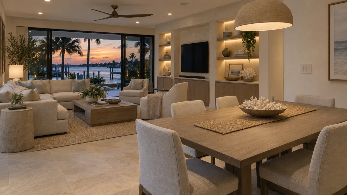
Specify environmental suitability from actual exposure. Bathrooms, enclosed laundry areas, and storage outside the conditioned envelope may differ in humidity, condensation, and temperature. In an Alys Beach home, coastal styling is not evidence of moisture or corrosion resistance. Use the complete fixture assembly’s location rating and manufacturer operating limits. Damp- or wet-location suitability alone does not establish corrosion resistance or suitability for every ambient temperature.
- Bathroom review: Is the face usefully illuminated without relying solely on wall glow? Are thresholds and bathing enclosures visible, and have bathing-area fixture and location restrictions been resolved?
- Storage review: Does the fullest intended arrangement preserve required fixture separation and light on the contents? Which shelving adjustments would invalidate the layout?
- Circulation review: Are steps, landings, and thresholds visible from both travel directions under normal settings, without exposed bright sources or abrupt bright-to-dark transitions?
- Utility review: Do fixtures preserve equipment working space, open-door access, removal routes, and access for lighting maintenance?
- Before ordering: Have the lighting designer and licensed electrician review these spaces together for conflicts among decorative choices, necessary illumination, environmental suitability, access, and applicable safety requirements. Use the approved criteria for Chapter 14’s acceptance checks.
11. Adapt the Design for Sleep, Aging, and Individual Comfort
Specify comfort by resident and activity, not by age. One person may need more light for small print while finding bright sources intolerable; another may struggle most with reflections or brightness changes. Identify the task, viewing position, and difficulty before choosing an adjustment. Where vision loss affects daily activities, a qualified vision-care or low-vision professional can help establish functional priorities for the designer. Lighting can support those activities without treating the underlying condition.
Evaluate task lighting with the resident’s usual glasses, reading material, and posture. More output is useful only when it improves visibility without adding glare or reflections. Compare a shielded, adjustable source with a broader illuminated task area: a narrow beam may spare another occupant but require frequent repositioning as the reader moves. Keep enough surrounding light to make looking away from the task comfortable. For residents sensitive to brightness changes, assess the reading position and its surroundings together rather than maximizing task brightness in isolation.
At the bed, assess each reading light from both pillows, including reclining and side-lying positions. A source hidden from its user may remain directly visible to the other sleeper. Each occupant should be able to adjust and switch off their own reading light without changing the other person’s setting. Locate controls against the actual mattress height, headboard, nightstand, and normal reach. A location convenient while sitting upright may be inaccessible while lying down; bedding, a water glass, or a mobility aid can also obstruct access.
Give each occupant reachable access to the nighttime route setting. Decide whether a shared room-off command should leave the other person’s reading light unchanged. Compare control indicators from the pillow in an otherwise dark room: a locator light may help one person find a button but disturb another, making adjustable or disableable indicators useful. Apply Chapter 6’s control framework using the accessibility checks below rather than adding a more elaborate bedside keypad by default.
Treat normal overnight movement as a separate lighting condition. Apply Chapter 10’s circulation criteria to the bed-to-bathroom or bed-to-door route, with enough visibility to recognize obstacles and the destination without routinely activating bright overhead lights. Low-mounted sources still need assessment for floor reflections and visibility from the opposite pillow. Choose the lowest level that supports confident navigation for the actual resident, not the lowest level the equipment can produce. Keep a reachable option for fuller illumination when needed.
Where nighttime lighting activates automatically, it should respond before the resident needs to step into darkness without routinely responding to a turning sleeper or pet. Timing must accommodate slower movement, pauses, and the return journey. A gradual transition may be comfortable, but a long fade-in can delay necessary visibility. Retain manual activation, and do not make essential route lighting depend solely on detection of continuous movement.
Residents reporting headaches, visual discomfort, or sensitivity to light modulation should evaluate representative equipment during ordinary activities at intended brightness settings, including the lowest useful level. Stop the trial if discomfort develops; there is no benefit in enduring symptoms to complete it. Modulation may not appear as obvious flicker, so visual inspection cannot establish its absence. Request relevant manufacturer performance data and use Chapter 7 for equipment compatibility review. Neither a comfort label nor phone-camera banding establishes individual tolerability. New or persistent symptoms warrant healthcare advice; product comparison is not a diagnostic test or medical intervention.
Choose the smallest amount of personal adjustment that resolves a recurring conflict. Separate task dimmers may suffice when occupants disagree about brightness. Tunable lighting is more defensible when residents value different color appearances and will use that choice. Compare a few directly selectable presets with continuous adjustment, retaining straightforward brightness control without requiring an app. Avoid routines that unexpectedly override a resident’s chosen setting. Warm-looking light can still be bright, and neither a warm setting nor a programmed routine guarantees better sleep.
- Reach: Try control samples from the intended lying or seated position. Can the resident operate them without stretching, twisting, or moving a mobility aid?
- Dexterity: Compare button size, spacing, operating force, and tactile feedback. Essential functions should not require precise gestures or sustained presses the resident finds difficult.
- Recognition: Assess label size and contrast at the intended light level. Use consistent positions, distinguishable shapes, or tactile markings rather than color alone; avoid essential commands hidden behind changing touchscreen menus.
- Recovery: Can the resident return directly to a familiar setting or request brighter light without cycling through unwanted scenes? Favor a clear, repeatable action over memorized button sequences.
12. Compare Proposals, Allowances, and Lifecycle Costs
Compare proposals at three levels: delivery of the approved scope, exposure to unresolved work, and ownership cost over a stated period. Build one owner-budget worksheet showing the base price, allowances already included, selected alternatives, separately funded exclusions, and owner-held contingency. Do not add included allowances twice. Keep future operating costs separate from the funds needed to complete the project.
Give every bidder the same dated room plan, fixture schedule, control narrative, and professional feasibility findings developed in earlier chapters. Require bidders to identify departures, omitted quantities, and assumptions; share scope-changing clarifications with all bidders. Compare a compliant base proposal first, then alternatives. A lower price achieved by omitting fixtures, simplifying controls, or excluding restoration is a scope difference, not necessarily a saving.
Require separate prices for design, equipment, electrical labor, programming, professional access work, surface restoration, and administrative tasks. Equipment pricing should identify accessories, freight, and applicable taxes. Separate known corrective work from the planned installation. Programming should state the included setup, instruction, and adjustment visits by reference to the control narrative. Administrative pricing should distinguish contractor service charges from authority fees.
Treat each allowance as a priced assumption rather than a fixed commitment. Compare its quantity, product standard or work scope, included labor, markup, reconciliation method, and credit for unused funds. An exclusion provides no funding. For concealed conditions, identify the investigation included in the base price, the basis for pricing discoveries, and the authorization threshold for additional spending. Set contingency according to unresolved risks; it is neither a contractor allowance nor automatic permission to spend.
Define restoration boundaries carefully. Closing an access opening may exclude texture matching, surface preparation, and repainting a continuous wall or ceiling. Establish who budgets the larger finish area if a localized match proves unacceptable. For unselected or unavailable fixtures, determine whether an allowance covers only the product or also changed accessories, installation labor, and controls. Where investigation must precede reliable pricing, compare the funded investigation stage separately from the still-uncertain construction scope.
Compare procurement exposure alongside equipment price: quote expiration, estimated versus confirmed lead times, deposits, cancellation rights, nonreturnable products, return deadlines, restocking charges, and freight. Identify who pays for storage and additional mobilization after delayed deliveries. Substitutions must meet the earlier design and compatibility criteria; compare their net effect on redesign, testing, controls, labor, and schedule, not just their purchase-price difference. Establish who can approve a substitution before an order becomes binding.
Read product warranties separately from workmanship coverage. Compare duration, exclusions, claim administration, and coverage for diagnosis, elevated access, removal, shipping, reinstallation, and finish repair. A replacement component does not necessarily cover any of that labor. For owner-supplied equipment, clarify responsibility for incorrect orders, shipping damage, defective products, and repeat visits. Include uncovered service exposure in the comparison rather than assuming reimbursement.
Estimate annual energy for each group as quantity × documented input watts × annual operating hours ÷ 1,000. Use complete fixture input, including driver losses where applicable, not incandescent-equivalent wattage. Account for documented standby consumption over the appropriate hours without double-counting it. Apply the homeowner’s actual usage-dependent electricity rate; fixed bill charges generally remain. Use the same realistic occupancy assumptions across proposals, including seasonal vacancy where relevant. Do not assume a halfway dimmer setting halves consumption or credit automation savings without evidence.
Over a common ownership period, compare initial cost, energy, subscriptions, professional service, replacement components, and associated access or restoration. State the sources and uncertainty of service and replacement assumptions; rated LED life is not a warranty or a replacement date for every component. Show uncertain costs as ranges or unresolved items. Before award, reconcile the completion budget with payment milestones and identify cash commitments due before delivery, installation, and acceptance.
- Approvals: Name who verifies required approvals and inspections with the applicable authority, handles submissions, and budgets fees. Mark each fee as included, allowed for, or excluded.
- Supply: Assign ordering, delivery checks, storage, damage claims, and returns. Identify who bears losses on canceled or changed orders and link payments to defined deliverables.
- Coordination: Name the lead party responsible for scope gaps among electrical, access, finish, structural, and network trades. Identify included coordination charges; leave work sequencing to Chapter 13.
- Compatibility: Reference Chapter 7’s verification requirements. Assign responsibility and costs for design errors, unauthorized substitutions, defective products, and installation errors, including how disputed troubleshooting charges will be resolved.
- Completion: Include Chapter 14’s acceptance and closeout deliverables in the price. Define treatment of unresolved items and any retained balance at the final payment milestone.
13. Coordinate Installation and Protect Finished Interiors
Turn the approved design and Chapter 12 responsibility assignments into a room-by-room schedule with explicit release points. The sequence should be investigation, dependent product approval, procurement, installation, concealed-work review, initial operation and programming, then finish restoration. Some activities can overlap, but the contractor should identify who authorizes each handoff. Making an unfinished area safe between visits is not the same as releasing it for permanent closure.
Complete targeted professional investigation before ordering products whose fit or installation depends on concealed conditions. Unaffected purchases may proceed separately. Before disruptive removal, confirm that the needed fixtures, controls, accessories, and mounting components are on site and checked for damage and completeness. If early access is necessary to establish feasibility, agree on its extent, expected duration, and temporary protection rather than treating a delivery estimate as a firm installation date.
Agree on proposed wiring routes and access locations before licensed professionals begin wiring or structural access. Mark openings on plans or photographs, distinguishing acceptable visible locations from routes still awaiting professional verification. Compare alternatives by total restoration area, repair visibility, rooms affected, and future service access, not simply by the number or size of holes. Access through a less prominent adjoining room may protect a decorative ceiling but create another room closure and finish repair.
Set restoration boundaries while routing options are still open. Continuous plaster, patterned wallcoverings, decorative woodwork, and finishes that are difficult to match can make localized repairs conspicuous. Decide whether the intended result requires a patch, refinishing an entire ceiling plane, or work extending to a natural architectural boundary. Record existing surface conditions and settle the location and appearance of any permanent service access before finish trades begin.
For an occupied home, identify closed rooms, usable circulation routes, work hours, and conditions for returning each area to use. The electrician should identify areas affected by planned power interruptions; these may extend beyond the room under construction. Establish advance notice and expected duration, accounting for essential powered equipment and work-from-home needs. If the phase cannot preserve safe circulation or essential household functions, arrange another occupancy plan rather than relying on improvised access through the work zone.
Assign furniture relocation and protection before crews arrive. Artwork, fragile objects, and electronics may need removal rather than coverings alone. Floor protection must suit the finish and anticipated ladder or lift traffic. The contractor should coordinate dust containment, collection during cutting, debris routes, and ventilation measures without spreading dust into occupied rooms. Keep residents and pets outside work areas. Daily cleanup should include securing incomplete areas and clearly identifying which rooms remain unavailable.
Use one coordination lead for trade handoffs. The lighting designer resolves fixture alignment and visible layout details before openings are made. The electrician and professional responsible for mounting support coordinate attachment requirements before finishes conceal the work. Finish trades receive opening, trim, and finishing-assembly requirements early; trimless fixtures may require staged visits rather than one final installation. Where connected controls depend on network infrastructure, the network specialist completes that work before setup and programming.
Schedule required concealed-work reviews and applicable inspections before closure. Allow the electrician and controls programmer enough initial operating time to identify problems that could require renewed access. Where the fixture system permits, keep final decorative components protected until dusty finishing work is complete. Restoration proceeds after the coordination lead releases the area, with time allowed for finish drying before final assembly and adjustment. Final acceptance belongs to Chapter 14; these earlier checks prevent avoidable reopening.
When concealed conditions, unavailable products, or owner requests alter the plan, pause the affected work and obtain written change approval. State the reason, proposed revision, visible effects, price and schedule consequences, and any reopening or refinishing of completed work. Recheck substitutions against the approved fixture schedule and Chapter 7 compatibility requirements before purchase. Unaffected work may continue only if it will not foreclose the pending choice.
For seasonal occupancy, work backward from the intended arrival date while reserving time for adjustment and return visits. Identify who admits crews, receives and checks deliveries, and provides secure storage under manufacturer-specified conditions. Name an available decision-maker, define the representative's authority, and set response windows for questions that could stop work. Schedule owner participation after dark as an appointment, not an assumed first-evening obligation. Leave room between installation and occupancy for programming, finish drying, cleaning, and correction of unresolved work.
14. Commission the Installation and Document Acceptance
Commission the installed system against the approved room plan, fixture schedule, control narrative, Chapter 7 performance criteria, and authorized changes. Arrange a joint walkthrough with the electrician, lighting designer, and programmer as applicable, including time after dark. Acceptance should establish whether agreed results were delivered, not introduce new design criteria.
Mark each check Pass, Fail, or Deferred. Pass means the approved requirement was demonstrated; Fail identifies a discrepancy; Deferred identifies an incomplete check, its reason, responsible party, and return date. Record the tested plan and configuration versions. Use Chapter 2’s Observation record for symptoms and supporting photographs, linking those records to punch-list items rather than creating a separate reporting template.
- Nighttime distribution , With furniture, artwork, and normal window coverings in place, compare individual zones and combined scenes with the approved room plan. Observe intended tasks from actual seated and standing positions. Check occupant shadows, direct glare, reflected sources, accent placement, and circulation transitions. Identify discrepancies by fixture or zone. If specified illuminance targets apply, attach the lighting professional’s measurements and test conditions; photographs locate concerns but do not establish light levels. Defer checks materially affected by missing furnishings.
- Switches and multi-location controls , Operate every designated control location and confirm that only the intended groups respond. Test the specified sequence from different entrances, including operating one control after another has changed the lights. A working switch is not a pass if it controls the wrong zone or leaves another required location ineffective.
- Dimmers, keypads, and scenes , Check labels, raise/lower actions, saved levels, specified secondary button functions, scene membership, and transitions against the control narrative. Include scene activation after manual adjustment and any specified master command. Following a correction, retest affected shared functions as well as the corrected button.
- Sensors , Demonstrate arrival, representative occupied activity, departure timeout, and manual override. Confirm that normal activity does not produce unintended shutoff under the agreed operating conditions. Restore and record final settings after any shortened demonstration timeout. Defer daylight-dependent checks until suitable daytime conditions are available.
- Dimming and light quality , Apply Chapter 7’s approved criteria at full output, intermediate levels, and the agreed minimum, including startup at a saved low setting. Record visible instability, delayed or inconsistent startup, unwanted noise, and mismatched color within intended matched groups as acceptance issues. In the Chapter 2 Observation record, identify the equipment, control action, setting, and symptom; homeowner electrical testing is not part of acceptance. Raising the minimum is not a pass if it defeats the approved low-light requirement.
- Recovery behavior , Have the contractor demonstrate the applicable interruption cases established in Chapter 8. Distinguish internet loss from local-network loss where both are acceptance requirements. The electrician manages electrical interruptions; the network specialist manages network changes. Coordinate demonstrations around other household equipment. Check available wall controls, restored light states, scenes, schedules, and required recovery actions. Record actual behavior and recovery time. Manufacturer-described behavior that has not been demonstrated remains untested.
- Closeout completeness , Reconcile project records into an as-installed set: room-linked fixture and control identifiers; installed model, lamp, and driver references as applicable; final scene, dimming, and sensor settings; supported configuration backups; electrician-provided circuit identification; manuals; purchase and warranty records with claim contacts; and required inspection or approval documentation applicable to the work. Confirm that identifiers match the plan and acceptance checklist. Missing records remain open items. Inspection approval does not establish visual or functional acceptance.
- Punch-list responsibility , Give each failed or deferred item a unique number and link it to the relevant observation and unmet criterion. Record its category, coordinating party, corrective action, target date, and retest result. Assign installation defects to the installing contractor, programming corrections to the programmer, and suspected product problems to the contractor coordinating with the supplier or manufacturer. Keep a coordinator assigned while the cause is unresolved. Separate owner-requested design changes from nonconforming work and route them through Chapter 13’s change process.
- Acceptance decision , Close corrections only after retesting under the relevant conditions. Identify requirements passed, exceptions expressly accepted by the owner, and unresolved items with follow-up responsibility. Do not convert deferred checks into passes to complete the paperwork. Preserve the final tested configuration in the closeout package before the Chapter 15 occupant handoff.
15. Hand Off Lighting to Guests, Caretakers, and Seasonal Occupants
Prepare three practical handoff tools: a short guest card, an arrival-and-departure checklist, and a restricted access record for the homeowner and manager. Base them on the accepted control behavior from Chapter 14. Keep technical closeout records separate from the instructions someone needs on arrival.
The guest card should match visible control labels and explain ordinary room lighting, brightness adjustment, useful scenes, and Off. Identify commands that affect other rooms, expected sensor shutoff behavior, and any wall control that must remain on to supply connected lamps. Include the verified local fallback for an internet outage and one current help contact. Guests should not need administrator credentials or an app installation. If essential operation still requires coaching, simplify the interface rather than lengthening the card.
Apply the ownership arrangement from Chapter 8 to each caretaker’s duties. Someone making in-person inspections may need no remote account. A rental manager may need scene activation and occupied-mode selection, but not permission to remove devices, invite users, or change integrations. Use named accounts and expiration dates where supported; keep permitted duties and access end dates in the restricted record. Where routine operation cannot be separated from administration, retain administrative access with the owner or designated provider instead of sharing the owner’s login.
Distinguish permission to select an approved mode from permission to rewrite recurring schedules. Name the person who can approve persistent changes and the person who receives unresolved readiness reports. Before remote commands affect multiple rooms, confirm occupancy with the responsible person: an empty booking calendar does not establish that cleaners, contractors, or residents have left.
Complete the arrival checklist before occupants are expected after an extended absence. This is a readiness check against the accepted instructions, not repeat commissioning. Confirm actual illumination in person; an app showing an active scene does not prove the lights responded. If essential lighting is unavailable, the manager should arrange resolution before arrival rather than leave guests to troubleshoot.
Departure routines should distinguish a brief vacancy from an extended absence. State which lights turn off, which schedules pause or continue, whether sensors remain active, and how occupied operation resumes. A departure scene may change light levels without changing schedules or sensor behavior. Retained lighting uses energy and may suggest occupancy, but it does not replace a separate security plan. Do not make departure dependent on shutting down electrical circuits or network equipment.
For lighting problems, use the Observation record established in Chapter 2; do not create a separate guest reporting form. Make that record available without administrator access and identify where guests should send it. Accept observations from ordinary use without asking anyone to reproduce a fault. The manager should acknowledge receipt and route the record to the appropriate service contact. For unusual heat, burning odors, sparking, or visibly damaged equipment, stop using the affected light or control, keep others away, and promptly contact the responsible person; immediate danger requires emergency assistance. Do not attempt repairs or repeated resets.
When a management company changes or a resident leaves, revoke outgoing access, replace shared credentials they knew, and reassign notifications and schedule responsibility. Remove resident-specific presence triggers so a departed person’s phone cannot continue influencing the home. At a sale, follow the provider’s supported ownership-transfer process, including any hub or subscription dependencies. Coordinate verification of the buyer’s control with removal of the seller’s remote access and personal integrations. Keep personal credentials out of transfer documents. Date revised handoff tools and replace obsolete guest cards.
- Arrival, Walk the entry and circulation route using intact ordinary controls. Confirm essential room lighting responds and labels match their effects. Record discrepancies through Chapter 2’s Observation record without repeated attempts.
- Arrival, Check the displayed date, time, and time zone for schedule-dependent controls, including standalone timers. Review the next scheduled event and any daylight-saving setting the system provides. Refer incorrect settings to the person authorized to change them.
- Arrival, Select the documented occupied mode. Confirm absence routines are paused as intended and check for temporary overrides or expiration times that could change lighting during the stay.
- Arrival, Confirm the guest card is present, its help contact is current, and the responsible manager knows about unresolved issues before releasing the home for occupancy.
- Departure, Confirm nobody still needs the affected lighting, activate the approved routine, and verify its visible result. Record intentionally retained lighting, active schedules, the planned return date if known, and who will restore occupied mode.
16. Maintain the System and Plan for Future Replacement
Use the commissioning closeout package as the maintenance baseline, adding service history rather than building another inventory. The aim is to preserve useful light and consistent appearance while keeping eventual replacement manageable, not to reopen the design at every service visit.
Build the maintenance calendar around manufacturer cleaning and service instructions, distinguishing prescribed intervals from owner-selected reminders. Where no interval is given, choose an observation schedule based on actual dust accumulation, humidity exposure, and occupancy; shorten it if deterioration develops. For a seasonally occupied home, combine observations with Chapter 15’s arrival checks and arrange professional service when someone can provide access and review the result.
Limit homeowner cleaning to intact exterior surfaces reachable from the floor without removing shades, lenses, trim, or covers. Follow manufacturer shutdown, cooling, and cleaning instructions, using approved materials and never spraying liquid into equipment. Elevated access, disassembly, lamp replacement, and electrical servicing belong to licensed professionals. Active moisture, scorching, or an operating odor calls for stopping use of the affected equipment and obtaining prompt professional assessment, not cleaning it.
Use Chapter 2’s Observation record for maintenance concerns. In its notes, describe whether the change is new, persistent, or worsening and whether it followed service or a software update. Compare gradual output changes at the same scene setting under similar daylight and furnishing conditions. Needing a higher setting is evidence of changed performance, not proof of LED deterioration. Photographs can track finish damage or moisture marks, but automatic exposure prevents reliable comparisons of light output. If task visibility has declined, professional measurement may help separate equipment changes from room conditions or resident needs.
Track recurring moisture marks, corrosion, and finish deterioration before buying replacements. Repeated cosmetic cleaning can obscure progression without resolving its cause. Humidity exposure may be relevant, but observations alone cannot establish the source of damage. Ask the servicing professional whether an unresolved environmental condition could also affect a replacement.
Retain a modest reserve of approved spare lamps where matching a group matters, following the manufacturer’s storage guidance. Preserve packaging and exact ordering suffixes; add missing finish codes, approved component references, purchase records, and discontinuation notices to the existing fixture schedule. A successor product is a candidate, not automatically an equivalent. Avoid stockpiling proprietary drivers or modules without professional confirmation of their serviceability and storage requirements: warranties may run during storage, and later revisions may limit usefulness. Apply Chapter 7’s compatibility review to substitutions.
Treat firmware changes as controlled maintenance. Assign someone to monitor support notices and distinguish security or reliability corrections from optional features. Before an update, record the installed version, save a configuration backup where supported, and establish available recovery options rather than assuming rollback exists. Schedule changes when normal operation can be checked and support is available. Where automatic updates cannot be deferred, confirm who receives notices and failure alerts. Use the system provider for specialist-dependent updates.
Periodically verify owner access and recovery methods, remove obsolete administrator permissions, and protect backups that contain sensitive information. Keep credentials out of shared service notes; use Chapter 15 for provider transitions. Factory resets are not routine maintenance. Loss of security support warrants review of continued connected operation and migration options even when ordinary lighting still works.
Use the replacement criteria below after professional assessment establishes the available repair path. At the same review, compare service history with room use and resident needs. Changed reading needs, a newly used work area, or repeated service visits may justify a targeted improvement. Define the affected task or smallest coherent zone, then revisit only the relevant design decisions.
- Single-unit replacement: Favor this when an approved component repair or fixture replacement restores function without a conspicuous mismatch. For an integrated fixture with an unavailable driver, establish whether an approved replacement assembly exists before replacing the complete fixture. Compare a proposed replacement beside retained fixtures; matching specifications do not ensure that new and aged LEDs will look identical.
- Matched-zone replacement: Consider this when a single replacement would visibly disrupt a continuous wall wash or coordinated group. Balance consistency against discarding functional equipment, installation disruption, and future component availability. Replace the smallest visually coherent group, not automatically the entire room.
- Broader control-system review: Escalate when essential controls are unsupported, unavailable proprietary components affect several zones, or recurring service problems have no sustainable repair path. Compare continued repair, staged migration, and broader replacement, including which existing fixtures can remain and how lighting will operate between stages. One failed integrated fixture or unavailable driver does not by itself justify replacing the control system.
About this guide: This resource provides general homeowner education, not a remote diagnosis. Actual conditions, code requirements, equipment, and safe repair options must be evaluated at the property.