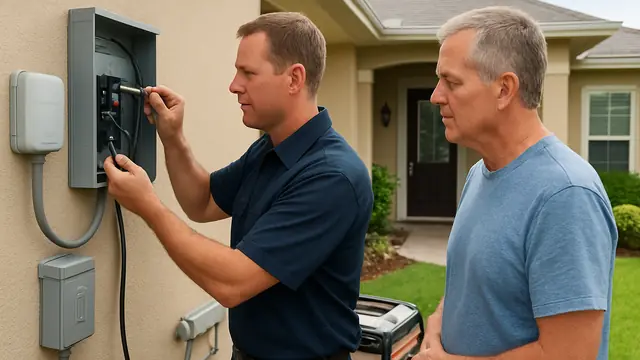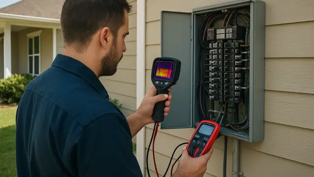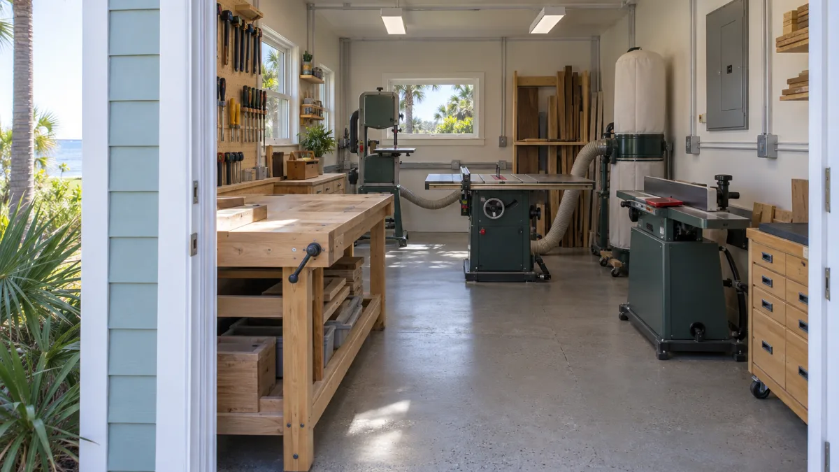
Do not remove an electrical panel cover, touch exposed conductors, bypass protection, or repeatedly reset a fault. Keep clear of smoke, sparks, burning odors, hot equipment, standing water near electricity, and downed lines, then call qualified help.
1. Define What the Workshop Must Actually Support
Start with the work the building must support, not a request for outlets. The first homeowner deliverable is a functional brief: intended activities, who will use the space, operating patterns, priorities, and exclusions. Approve that brief before requesting a circuit layout. It gives the designer a basis for distinguishing necessary functions from optional conveniences and prevents an undefined wish for “workshop power” from driving the project.
Describe complete activities rather than broad hobby labels. For woodworking, identify whether the scope includes rough stock preparation, machining, sanding, assembly, or finishing. Supporting tasks such as dust capture belong in the brief even though their equipment requirements come later. For metalworking, distinguish small-part assembly from grinding, welding, or heat treatment; each introduces different process and building questions. Decide which operations must happen in this building and which can remain elsewhere.
Crafts, storage, and household projects need equally clear boundaries. Sewing and paper crafts emphasize usable work surfaces and visibility; resin work and ceramics may introduce chemical or heating processes that need separate review. Storage is not necessarily an inactive use if batteries will charge or environmental control will run while nobody is present. Occasional repairs may be well served by a limited workspace rather than provisions for sustained machine production. Describe the intended result without prematurely selecting circuits or supply equipment.
Establish the use status early. Customer visits, paid production, employees, or instruction are reasons to seek a property-specific land-use and occupancy review, not proof that a particular classification applies. Tell the appropriate planning or building authority and qualified design professionals what will occur, how often, and with how many people. If the project depends on that use being allowed, resolve its feasibility before committing to equipment or construction for it. An electrical design does not establish permission to operate a business or hold classes.
Separate commitments into three groups. Opening-day essentials are functions whose absence would prevent the intended work. Likely additions have a defined purpose and credible timing; identify whether preserving their feasibility is important enough to affect today's scope. Speculative wishes remain outside the base project unless deliberately promoted to a commitment. This is a priority decision, not an exercise in guessing extra electrical capacity. Equipment data and future-use scenarios belong in Chapter 4; supply alternatives belong in Chapter 5.
Record how the workshop will operate. Include typical and longest sessions, maximum users, and whether users will work independently or share one task. Identify noise-sensitive periods and whether noisy supporting equipment would make the intended schedule impractical; do not assume a local restriction. List equipment expected to remain energized after departure and the reason for doing so, subject to manufacturer instructions and later professional review. If comfort or humidity control is essential to using the room, state the expected occupied periods and whether control is also needed between visits. Chapter 11 addresses equipment selection.
Treat hazardous processes as an early decision gate. Planned combustible dust generation, spray finishing, flammable solvent use, or unusual heating and process equipment warrants screening by qualified specialists before ordinary workshop provisions are assumed suitable. Provide the proposed materials, processes, and approximate scale of work; do not classify the space yourself. Hold affected purchases and layout decisions until the review establishes whether the activity can be accommodated. Detailed process-load and air-handling coordination belongs in Chapters 9 and 11.
- Approve the purpose: List primary activities, necessary supporting tasks, and operations expressly excluded or assigned elsewhere.
- Set priorities: Mark each function as opening-day essential, a likely addition with approximate timing, or speculative. Identify acceptable limitations, such as keeping a particular process outside this project.
- Define the operating envelope: State user count, independent work patterns, session duration, noise-sensitive periods, occupied comfort expectations, and intended unattended operation.
- Resolve gates: Flag land-use or occupancy questions and hazardous-process reviews. Identify which purchases or construction commitments must wait and who will resolve each question.
- Move into design: With the brief approved, document existing conditions, map workstations, and gather equipment information in Chapters 2, 4. Licensed professionals then develop the electrical design and perform installation; the brief specifies outcomes, not wiring methods.
2. Document the Building and Its Existing Electrical Conditions
Establish an existing-condition baseline before counting any workshop wiring as reusable. The homeowner’s deliverable is a location-based photo record, relevant historical records, and a list of known symptoms and access restrictions. The licensed electrician’s deliverable is an assessment separating verified conditions from assumptions, with recommendations for retention, further investigation, or replacement. Working lights alone do not establish the condition of the supply.
Photograph the building and visible electrical equipment from normal, accessible floor or ground positions. Include overall views that locate closed enclosures, receptacles, lighting, and visible portions of the incoming supply. Record intact exterior labels only where readable without moving equipment or approaching damage. Keep electrical equipment closed, and do not reach behind storage to obtain a better image. Give each photograph a date and location so the electrician can connect close-up observations to the building.
Record defects as observations, not diagnoses: moisture staining above an enclosure, a cracked receptacle face, an enclosure pulling away from its mounting, or a cord passing through a doorway. Photograph abandoned-looking cables and improvised extension-cord supplies without touching, tracing, disconnecting, or moving them. A cable that appears unused may still be energized; an extension-cord arrangement is not evidence of an installed building supply. Note where staining or corrosion occurs, leaving its cause and required environmental corrections to the assessment in Chapter 12.
Add previously noticed symptoms with approximate dates and circumstances, including interrupted power, flickering, unusual sounds, or burning odors. Do not energize equipment or recreate a fault for the survey. Visible electrical damage warrants professional direction before further use of affected equipment. If smoke, sparking, or another immediate electrical hazard is present, leave the affected area, keep others away, and obtain emergency assistance.
Gather building plans, prior electrical invoices, inspection documents, available permit records, and earlier repair photographs. Sort them by date and identify which actually describe this detached building and which components were included. Distinguish proposed plans from records of completed work. An inspection applies to its stated scope and date; an invoice establishes only the work it describes. Keep previous-owner statements and personal recollections in a separate, unverified-history section. Gaps or conflicting descriptions are investigation questions, not proof that work is defective.
Ask the electrician to identify the supply’s origin, the equipment and loads it serves, and any unexplained connections or modifications. The existing-condition evaluation should address conductor identification and condition, wiring methods, protective devices, terminations, grounding and bonding, and evidence of overheating or physical deterioration. Its extent should be clear: exterior observation alone is different from professional inspection and testing of accessible components. Evaluation against planned demand belongs in Chapters 4 and 5, rather than being inferred from equipment appearance.
Retention decisions should be component-specific. Reuse requires adequate evidence of condition and suitability; partial replacement depends on the compatibility and condition of the retained portions and their connections. A defect at one device does not establish that the entire supply needs replacement, while an intact enclosure does not establish that concealed wiring is sound. Where inaccessible sections prevent a conclusion, the electrician should identify what further investigation would resolve the uncertainty before treating those sections as project assets.
Describe obstacles that affect the investigation: finished walls concealing routes, fixed shelving blocking views, stored materials restricting access, or building deterioration preventing safe entry. Homeowners should not remove finishes, open cavities, or enter unsafe spaces. Ordinary storage may be relocated where it is safe, but items contacting suspect electrical equipment should remain undisturbed pending professional direction. Have the appropriate licensed professionals define any necessary structural access or repairs, including responsibility for restoring finishes.
Before reuse enters the planning assumptions, review the assessment using the questions below. Unresolved conditions can remain open during early planning, but they must not silently become confirmed infrastructure in a proposal.
- Is the supply origin verified, and are shared loads, unexplained cables, or undocumented alterations still unidentified?
- Which conductor characteristics, connections, and route sections were actually evaluated? Which are concealed, inaccessible, or inferred only from records?
- Does each proposed retained component have a status of verified for retention, conditional on further evaluation, or undecided?
- What access or building work is needed to complete the assessment, who is responsible, and what finish restoration may follow?
- Are current use restrictions distinguished from future upgrades? Is any reuse-dependent purchase or construction decision held until the relevant uncertainty is resolved?
3. Map Workstations, Receptacles, and Everyday Movement
Settle the working layout before selecting receptacle locations. Prepare a scaled floor plan, trace how tools and materials move, then mark preferred connection zones. These are functional requests for the licensed electrician, not installation instructions. Resolve major layout conflicts before fixing benches in place or approving electrical installation locations.
Start with interior dimensions, doors and their swings, windows, fixed storage, benches, and machine footprints. Use movable shapes to compare arrangements. Add drawers at full extension, cabinet doors, adjustable machine tables, and the positions from which users operate controls. Measure from stable building features rather than furniture that may move.
Around each machine, draw an operating envelope that includes the operator, moving machine components, and material infeed and outfeed. Use the stock sizes you expect to handle, not just the machine’s base dimensions. Then trace routes for entering, carrying materials, moving finished work, and leaving. Where a walking route overlaps active material travel, revise the arrangement or identify activities that cannot occur together. Do not treat an exterior doorway as dependable extra outfeed space; any layout relying on an open door has a constraint that must be resolved.
For movable tools, show parked and operating positions separately. Compare three options: a wall connection, a professionally designed overhead connection, or a furniture change that keeps the tool nearer a suitable wall. Wall connections work best when the cord stays outside circulation and material paths. Overhead connections can avoid floor crossings but must accommodate tall workpieces, overhead storage, tool movement, support, and user reach. Rotating a bench or changing a machine’s operating position may eliminate those complications. An overhead connection is not an extension cord hung from the ceiling.
Check cord reach from the actual cord exit point, not the center of the tool. Record the available factory-cord length and trace its usable route to the proposed connection zone. Allow for plug projection, cord bends, and movement without tension; a straight-line measurement can conceal an unusable route. Keep cords away from cutting areas, moving parts, hot surfaces, sharp edges, and material travel. Check each intended operating position, including the far end of a shared bench. If the route does not work, revise the layout or have the electrician evaluate an equipment-specific solution. Extension cords and power strips should not be the permanent operating plan.
Judge accessibility with the workshop furnished. Users should be able to see the connection and grasp the plug normally without reaching behind heavy equipment, unloading shelves, or crawling beneath a fixed bench. Leave room for the plug and cord without drawers closing against them or knees striking them. For a seldom-unplugged machine, preserve access for exterior observation and eventual servicing rather than assuming the connection can disappear behind storage. Mark preferred heights and reach zones as user needs; the electrician determines final placement and installation details.
Check the layout for the actual users. Left- and right-handed work can put a portable tool’s cord on different sides of the cutting or assembly area. Seated users or people with limited reach may need a connection nearer the front or side of a bench, but projecting plugs must not crowd passageways. At shared stations, locate connection zones so neither person must reach across the other’s active work. Verify that controls remain accessible when both stations are occupied, drawers are open, and materials are in position. A full-size furniture mock-up can expose reach and circulation problems that look harmless on paper.
- Use a clear legend to distinguish machine footprints, operating envelopes, material paths, walking routes, and door or drawer swings.
- Give each workstation and tool an identifier matching the equipment inventory in Chapter 4. Show fixed, parked, and operating positions with dimensions.
- Mark preferred connection zones, cord exit points, measured available cord lengths, suitable cord routes, plug-clearance needs, and user reach requirements.
- Flag unresolved choices: wall versus overhead service, alternate furniture arrangements, shared-use conflicts, and any position that works only after rearrangement.
- Have the electrician resolve connection feasibility before the layout is finalized. Keep electrical ratings in the Chapter 4 inventory and panel working-space decisions in Chapter 7 rather than duplicating them on this functional drawing.
4. Build an Equipment Inventory and Simultaneous-Use Profile
Prepare two linked planning tools: an equipment inventory showing electrical input requirements, and a simultaneous-use profile showing which loads must operate together. The inventory establishes what may be connected; the profile establishes how the workshop will actually be used. Together they give the electrician a basis for calculating demand without assuming either that every machine runs at once or that only the tool in the operator’s hands draws power.
Give each load an identifier tied to the workstation plan. Include tools, dust collection, compressors, individual chargers, lighting, heaters, cooling, dehumidification, ventilation, and anything left operating between visits. For identical items, record quantity and how many may operate together. For packaged machines, establish whether the stated input includes accessories or whether those accessories need separate entries. This prevents both omissions and double counting.
Collect ratings from intact, normally accessible labels and the manufacturer’s instructions for the exact model. For a proposed purchase, use model-specific technical documentation rather than a product-family advertisement. Record electrical input as labeled: amperes, watts, or volt-amperes, with the associated voltage and operating mode. These quantities are not interchangeable. Marketing or peak horsepower does not establish electrical demand, and a machine’s mechanical output or a welder’s output current is not its supply input. Plug appearance is not a substitute for these ratings. Leave missing or conflicting information unresolved rather than borrowing data from a similar machine.
Describe operating sessions by task. Identify loads that are necessary together, overlaps that are merely convenient, and equipment that may start without an operator’s immediate action. A cutting profile should account for the saw, dust collection, lighting, and any background loads, including a possible compressor recharge cycle. A single operator may rule out simultaneous operation of two hand-controlled tools, but does not rule out charging, heating, or automatic cycling. Include a separate profile if a second user materially changes the overlap.
For each profile, record expected session length, the longest credible uninterrupted operation of each load, and whether it runs steadily, briefly, or in repeated cycles. Describe what causes automatic cycling and whether it can occur during production or while the building is unoccupied. Do not treat average daily energy use as a substitute for this profile: low energy consumption can coexist with substantial short-duration demand. Likewise, an informal estimate that a tool runs only occasionally does not establish a permissible reduction in its calculated load. The electrician determines the applicable treatment of duration and intermittent operation.
Represent future equipment as separate, named scenarios rather than an extra percentage added to today’s total. Identify whether each addition replaces an existing load or operates alongside it, its documented input rating or supplier-supported range, and the overlap it would introduce. Keep uncertain choices visible. Before committing to equipment whose requirements remain unresolved, ask which missing specifications could change the supply decision. Supply alternatives belong in Chapter 5; detailed motor and specialized-process compatibility reviews belong in Chapters 8 and 9.
- Equipment entry: identifier, manufacturer, exact model, quantity, owned or proposed status, rated supply voltage, phase, frequency, and labeled input ratings. Tie each rating to its source and stated operating mode; note uncertainty about the actual configuration.
- Manufacturer requirements: capture any specified supply-circuit requirements, minimum circuit ampacity, maximum overcurrent protection, connection method, accessory inputs, and operating-duration limits. Include published starting-current or duty-cycle data when available, without trying to derive missing values.
- Session entry: task, number of users, duration, continuously operating loads, manually switched loads, automatic loads, and necessary versus optional overlaps. Use observations from ordinary operation; do not force cycling or stage an overload to obtain information.
- Restriction check: identify which optional overlaps you would genuinely give up. A restriction on discretionary charging may be manageable; a restriction that depends on predicting an automatic compressor start may not be. Do not exclude a necessary supporting load merely to make the demand appear smaller.
- Professional review result: request calculated demand for the opening-day profile and each defined future scenario, with assumptions and unresolved inputs identified. Have the electrician distinguish the formal demand calculation from the assessment of starting, cycling, and usable operating combinations. Any proposed operating restriction should be explicit and workable. A homeowner-added nameplate total is not a circuit or feeder design.
5. Choose the Workshop Supply Architecture
Choose the supply arrangement after the equipment demand assessment in Chapter 4 and before committing to route construction or supply equipment. The homeowner’s decision is whether the proposed arrangement supports the intended work at an acceptable level of installation complexity and operating restriction. The electrician’s task is to establish which alternatives are technically suitable, including whether the existing property supply can serve them.
A limited branch-circuit supply may suit a small workshop with modest, stable needs, such as lighting, charging, and occasional portable-tool use. Its advantage is a simpler arrangement without a workshop distribution panel. Its main disadvantage is limited adaptability: adding independent loads later may require replacing the original supply rather than extending it. Ask whether it supports the opening-day brief without inconvenient restrictions and whether those restrictions will remain credible as the workshop develops. The electrician must determine the permitted detached-building supply arrangement; progressively adding separate circuits from the house is not an unrestricted expansion option.
A feeder serving a workshop distribution panel is usually the stronger candidate when the workshop needs several circuits, multiple equipment voltages, or provision for identified additions. It provides a central supply from which workshop circuits are distributed. Compare it with the limited option on the basis of expected changes, not simply the number of tools owned today. A feeder can make later circuit additions less disruptive, but only within the supply design’s limits. Panel location, circuit grouping, and protective provisions are addressed in Chapter 7.
Before assuming a service upgrade is necessary, have the electrician assess the workshop demand together with the household loads that share the source and documented additions elsewhere on the property. The assessment should use the applicable load-calculation method, with professionally obtained demand information where that method permits. An electric bill’s total energy consumption does not establish available peak capacity. The useful conclusion is not merely whether the workshop can be connected, but which constraint, if any, prevents the proposed arrangement.
Separate a service-capacity problem from a connection or equipment-condition problem. The existing service might accommodate the demand while downstream distribution equipment needs alteration or replacement to accept the feeder. Alternatively, the source capacity may be insufficient even though a connection appears physically possible. The resulting options could include retaining the service, modifying downstream equipment, reducing the planned demand, using professionally designed load management, or upgrading the service. Request alternatives directed at the actual constraint rather than treating an upgrade as the default solution.
Distance can change the comparison substantially. The electrician should evaluate voltage drop along the relevant supply path, including downstream workshop circuits, under expected loading and relevant starting conditions. Use plausible installed route lengths, not straight-line building separation. A longer run may require larger conductors and compatible connection equipment, changing installation demands even when the calculated load stays the same. A workshop panel does not remedy voltage drop in its feeder. Compare each architecture using the same route assumptions; Chapter 6 addresses route feasibility, and Chapter 8 addresses machine-specific starting requirements.
Investigate a separately supplied arrangement when the existing source is substantially constrained, the workshop is far from practical connection points, or there is a genuine need for independent service. Separate metering concerns measurement and billing; it does not by itself create additional capacity or establish eligibility for another service. Feasibility depends on the serving utility’s accepted configurations, available supply characteristics, connection location, access requirements, and service terms. The electrician must coordinate the proposal with the utility and the authority having jurisdiction, with any applicable land-use or occupancy issues resolved separately. Compare ongoing account obligations as well as installation scope.
Choose future provision deliberately. Limiting demand may avoid infrastructure that would rarely be used, but a restriction that depends on users remembering every automatically cycling load is a weak basis for operation. If load management is needed to make an alternative viable, include its controls, dependencies, and operating consequences in the comparison. For identified future equipment, ask what must be installed now and what can reasonably wait. Where feasible, infrastructure that is difficult to replace later may warrant early provision even if additional supply capacity is deferred; distinguish those choices rather than purchasing an undefined allowance for growth.
- Select the architecture and source based on the professional capacity assessment, credible route lengths, and voltage-drop evaluation.
- Record why the principal alternatives were rejected and which operating restrictions or load-management provisions make the selected option viable.
- Identify the future equipment covered by the decision and the changes that would trigger a new supply review.
- Keep the selection provisional until unresolved capacity, route, utility, or approval dependencies are settled; do not order dependent supply equipment or authorize route construction prematurely.
6. Plan the Route Between Buildings
Compare routes as construction corridors, not just lines between buildings. With the supply arrangement from Chapter 5 established, identify at least one practical alignment and examine alternatives where crossings, trees, or access restrictions create substantial uncertainty. The homeowner’s contribution is a site sketch showing visible constraints and planned improvements; the contractor’s task is to establish buildable routes, entry points, and restoration requirements.
Walk accessible areas together and mark driveways, patios, retaining walls, gates, trees, planting beds, drainage swales, downspout outlets, and observed pooling. Include future additions, fences, parking areas, and patio extensions. Compare both the installed route and the temporary construction footprint: equipment access, excavated-soil storage, paving removal, and space needed at crossings. A corridor that fits the finished installation may still be impractical to construct without damaging adjacent improvements.
For an underground route, ask which obstacles can be avoided and which require a crossing. Open excavation exposes a continuous work area but can interrupt access and require extensive surface restoration. A professionally designed trenchless crossing may preserve paving, yet needs suitable launch and receiving areas and investigation of buried conflicts. Compare soil and groundwater conditions, drainage disruption, erosion exposure, tree-root impacts, and future excavation risk. Where significant roots are involved, arborist review may change the alignment or construction method.
For an overhead route, feasibility depends on suitable supports and attachments, required clearances, and the space beneath and beside the span. Review vehicle and equipment movements, nearby openings, trees at mature size, and access for future maintenance. Storm-driven branch movement can make a seemingly clear corridor unsuitable. Existing trees, fences, or roof edges are not presumed supports; building attachments require assessment of their supporting structure. Utility involvement is necessary where its facilities or service arrangements are affected. Compare these constraints with underground disruption rather than selecting by appearance or apparent distance alone.
Before routing is finalized, assign coordination of utility notifications, available site records, private locating, and any necessary professional investigation. The applicable utility-location service may not identify privately owned irrigation, yard-lighting wiring, or an existing workshop supply. Plans and surface markings do not establish exact depth or resolve every conflict. The contractor must determine where controlled exposure or other investigation is needed and confirm that notifications and markings remain valid for the work. Unresolved crossings should remain a construction hold, not an assumption buried in the estimate.
Choose entry points alongside the exterior corridor. An easy approach outside may encounter framing, masonry, finished rooms, or inaccessible storage inside. The electrician and appropriate building professional should coordinate structural limitations, penetration details, and future service access. Entries must preserve flashing and drainage paths and provide compatible pest exclusion; a bead of sealant does not substitute for a properly detailed penetration. Chapter 12 addresses environmental equipment selection. Here, the decision is whether the entry can be built and maintained without compromising the building envelope.
Before backfill or other concealment, have the installer photograph the actual route, crossings, bends, entries, and concealed transitions, using both wide views and details. Measurements should reference durable building corners or other fixed features. Retain an as-built route drawing with installer-recorded depths where applicable and locations of accessible pulling or junction points. Capture deviations from the proposed alignment, not merely the original plan. These route-specific records support later work but do not replace utility locating before future excavation.
- Approval gate: Select the corridor only after crossing feasibility, utility-location uncertainties, building entries, and access for construction are resolved sufficiently to define the work. Identify any investigation that must precede a final route commitment.
- Excavation responsibility: Name who performs excavation and specialty crossings, coordinates with the electrician, maintains temporary access and barriers, and authorizes backfill after required reviews. Include surplus-soil and debris disposal.
- Protection boundaries: Identify equipment travel paths, staging areas, and protection for paving, fences, drainage features, irrigation, and retained trees. Specify whether temporary removal and reinstatement of improvements are included.
- Concealed conflicts: Require work affecting the conflict to pause for assessment. Route changes must address their effects on crossings, entry details, and restoration through the change process in Chapter 14.
- Surface restoration: Define backfill and compaction responsibility, paving replacement boundaries, drainage reinstatement, and responsibility for construction-related settlement. State limitations on matching aged or unavailable surface materials.
- Landscaping limits: Distinguish protection of existing plants from replacement. Specify grading, sod or planting, irrigation restoration, and follow-up care rather than relying on a general cleanup allowance.
7. Design Distribution, Disconnects, and Circuit Protection
Review the distribution design against three operating questions: Can authorized users reach the disconnects? What stops working when a circuit trips? What provisions genuinely support future additions? The supply choice and load evaluation from Chapters 4 and 5 are inputs here, not decisions to repeat.
Reserve panel and disconnect locations on the furnished floor plan. Have the electrician establish the required working-space width, depth, and height, along with access and location restrictions for the actual equipment. Door-opening clearance alone is insufficient. Include shelving, benches, lumber storage, door swings, and the normal parking positions of rolling equipment. Reject a layout that depends on moving stored materials to reach a disconnect or clearing a workbench before professional service.
Compare locations by how reliably they will remain accessible, not simply by the shortest wiring route. Consider whether an approaching user can identify and reach the building disconnect without passing through a machine’s operating area. Ask which device disconnects the building supply and what remains energized after it is operated, including supply-side portions of equipment. A tool’s stop button, a branch-circuit breaker, and the building disconnect serve different purposes; none should be labeled as though they are interchangeable.
Group circuits by the consequences of losing power as well as by electrical demand. Separating general lighting from tool receptacles can prevent a tool-circuit trip from also darkening the room. Distinct bench-receptacle groups may localize interruptions, while a separately served unattended function may avoid being interrupted by ordinary tool use. Each separation should have an identifiable benefit; a circuit for every receptacle is not an operating objective.
Separation does not guarantee continuity. An upstream protective device or loss of the feeder can still interrupt several circuits or the entire workshop. Also identify dependencies: a tool may continue running after separately supplied dust extraction stops. Refer those dependencies to the coordinated-control review in Chapter 11, and address illumination after a supply loss in Chapter 10 rather than treating additional breakers as a complete solution.
Ask for a plain-language explanation of the detached building’s grounding and bonding arrangement. Grounding connects the system to earth where required; bonding connects conductive parts into an effective fault-current path so protective devices can operate. A ground rod does not replace that path. The explanation should identify the equipment-grounding provision, required grounding electrodes, and where neutral and equipment-grounding functions must remain separated. For an existing supply, use the assessment from Chapter 2 to resolve any required changes rather than inferring suitability from visible grounding hardware.
Ground-fault circuit-interrupter protection and arc-fault circuit-interrupter protection address different hazards. GFCI protection detects current imbalance associated with certain shock hazards; AFCI protection detects certain hazardous arcing conditions. Neither replaces overcurrent protection or covers every electrical hazard. The electrician must determine requirements from the applicable adopted rules, actual occupancy, locations, and circuit characteristics. Calling the space a workshop is not enough to establish which protection applies.
Review protection placement as an operating choice wherever compliant alternatives exist. Breaker-based and receptacle-based protection can differ in the extent of the circuit protected, the outlets interrupted, and the location of normal controls and indicators. A protective receptacle hidden behind fixed equipment can make an interruption difficult to identify. Ask which outlets each device affects and where users will find its controls. Equipment compatibility must be resolved without omitting required protection or treating repeated trips as normal operation.
Keep three future-readiness claims separate. Spare panel spaces are physical positions potentially available for compatible protective devices. Available electrical capacity depends on the supply, feeder, panel ratings, and evaluated loads, not the number of empty positions. A future circuit path is a feasible route from distribution equipment to an identified destination, with access preserved through planned finishes. A proposal may provide one without the others. For each likely addition already identified in the equipment plan, distinguish what is accommodated now from what still needs review or construction.
Use stable, specific circuit descriptions tied to equipment or recognizable locations, rather than entries such as “plugs” or personal nicknames. Disconnect labels should distinguish building shutdown from individual equipment shutdown and identify other sources or energized portions where applicable. Externally visible identification and a matching operating reference should let an authorized user understand shutdown boundaries without opening electrical enclosures.
- Before approving locations: confirm working space and disconnect access on the furnished plan.
- Before approving circuit grouping: identify which functions stop together and flag dependencies requiring coordinated controls.
- Before approving protection: confirm the applicable GFCI and AFCI decisions, coverage, and accessible control locations.
- Before accepting future-readiness claims: distinguish reserved spaces, evaluated capacity, and usable circuit routes.
8. Match Motor-Driven Tools to Their Electrical Requirements
Use the inventory from Chapter 4 and the supply decision from Chapter 5 to screen stationary machines before purchase. This review has three decision gates: can the available supply start and run the actual machine, are any configuration changes supported, and will its controls provide suitable stopping and restart behavior? Leave unresolved machines off the approved purchase list.
Motor starting is not simply a brief version of normal running. Many motors draw substantially higher current while accelerating, with the magnitude and duration depending on motor design, starting method, mechanical load, and supply conditions. Unlike a comparatively steady resistance-heating load, a motor needs sufficient torque to reach operating speed. Starting voltage drop can reduce torque and prolong acceleration. Slow starting or tripping calls for diagnosis, not a larger breaker; motor overload protection and branch-circuit protection have different functions that the electrician must coordinate.
The driven equipment changes that assessment. Saws and planers accelerate blades, cutterheads, and drive components before engaging stock; unusually long acceleration may indicate either an electrical or mechanical problem. Dust collectors accelerate impellers whose inertia and fan characteristics affect startup. Compressors add a different concern: automatic restarting, potentially while another tool is operating. Their pressure-control and unloading arrangements influence whether the motor can start as intended. A compressor that struggles to restart needs equipment-specific investigation, not an assumption that its circuit is too small.
For used equipment, collect accessible label photographs, the model-specific manual, and the seller’s account of motor replacements, control changes, and starting problems. A replacement motor does not establish the requirements of the complete machine: feed motors, pumps, brakes, transformers, and electronic controls may need different supplies. Have a licensed electrician with appropriate machinery expertise reconcile the installed equipment with its documentation before committing. Missing diagrams, conflicting ratings, or unexplained modifications are purchase holds. Do not accept an improvised powered demonstration as a substitute for that assessment.
Manufacturer-approved voltage options can improve purchasing flexibility, but a dual-voltage motor does not necessarily make the whole machine dual-voltage. Controls and accessories may limit the available configurations. At a higher supported voltage, a motor generally draws less current for comparable output; this does not create additional horsepower or eliminate its power demand. Compare the total requirements of each supported configuration, including control components and the final connection. Any reconfiguration belongs to a licensed professional following the applicable manufacturer instructions.
Treat three-phase equipment as a separate feasibility decision. First establish whether a suitable supply is available; otherwise, compare a compatible machine against the complete conversion arrangement, not merely the converter’s purchase price. Phase converters and variable-frequency drives have different selection constraints, including input supply, starting torque, simultaneous motor operation, and control compatibility. A drive intended for one motor generally cannot be assumed suitable for powering a complete machine with multiple motors or electronic controls. Manufacturer-approved integration is especially important where braking, reversing, or safety controls are involved.
Conversion can also add enclosure, cooling, maintenance, and service-support needs. A variable-frequency drive may offer useful speed control, but the permitted speed range must account for motor cooling and the machine’s mechanical limits; electrical adjustability is not permission to overspeed a cutterhead or other driven part. If variable speed provides little benefit and conversion requires substantial control changes, a machine designed for the available supply may be the more practical purchase.
Review restart behavior for each stationary tool. A maintained switch may leave a machine commanded on when power returns; suitable no-voltage-release controls can require a deliberate restart. Automatic compressor cycling may be intentional, whereas unexpected restart of cutting machinery presents a different hazard. Establish the intended behavior through manufacturer information and professional assessment, with its demonstration reserved for Chapter 15. Do not interrupt and restore power yourself to investigate uncertain behavior.
Normal stopping, emergency stopping where provided or required, and isolation for servicing are distinct. A stop button may leave electrical parts energized, and a disconnect may leave moving parts coasting. Review the manufacturer’s controls, any braking function, disconnect provisions, and operator access together. The machine-specific checklist below supplies the compatibility references for the final circuit schedule; broader installation and handover records belong in Chapters 7 and 15.
- Identify the verified machine configuration: voltage, phase, frequency, installed motors, and any separately supplied controls or accessories.
- Reference the applicable manufacturer instructions for starting, connection, protection, and disconnecting provisions, plus any supported voltage change or conversion design.
- Specify the approved final connection and its matching circuit designation; do not leave an adapter or improvised connection as an unresolved procurement assumption.
- Record intended power-restoration behavior, stopping or braking limitations, and any conversion-related operating restrictions. Hold purchase or connection until discrepancies have an assigned professional resolution.
9. Evaluate Welders, Kilns, and Other Specialized Process Loads
Select specialized process equipment by exact model and intended process before asking for its connection design. For a welder, kiln, or heat-treatment furnace, the decisive questions extend beyond voltage: what electrical input does the selected version require, how does that input vary through a work cycle, and can the room accommodate the heat and process hazards? Use the equipment inventory and supply assessment from Chapters 4 and 5; this review determines whether the particular appliance and its proposed location are suitable.
A welder’s advertised welding amperage is output, not supply current. Its duty cycle states permitted welding time within a defined interval at specified output and test conditions. Higher-output welding may allow less operating time than lower-output work. Provide the electrician with the intended welding process and output range, plus the manufacturer’s input and duty-cycle data. Welder-specific electrical design provisions may apply; neither the output amperage nor an assumed average of welding and idle time is an appropriate homeowner basis for choosing a circuit. For multi-voltage models, check whether the proposed supply permits the output needed for the work.
Kilns and heat-treatment furnaces present a different operating profile. Elements may stay energized for long periods during ramp-up or recovery, then cycle during a temperature hold. A cycling controller does not establish that the electrical load is brief. The relevant information includes the intended ramp-and-hold schedule, maximum operating temperature, batch frequency, and whether successive batches leave little idle time. Two appliances with similar advertised power can therefore require different electrical treatment. Residual heat also matters: shutting off power does not immediately make loading areas, nearby storage, or servicing conditions safe.
Before the electrician specifies the connection, local disconnecting provisions, and protection, obtain the installation instructions for the exact model and electrical option. These must resolve rated input, voltage and phase, manufacturer circuit and protection requirements, permitted cord-and-plug or permanent connection arrangements, and disconnect instructions. Include any separate controller, vent unit, or cooling accessory instructions that affect shutdown or require an independent supply. Missing information about a used kiln’s replacement elements or a modified furnace controller is a purchase hold until the manufacturer or an appropriate professional resolves the equipment’s actual requirements.
Apply the process-hazard assessment from Chapter 1 to the proposed equipment position rather than repeating a room-wide review. Compare manufacturer clearances at the sides, rear, and overhead with the space needed to open lids or doors, load work, and service the appliance. Keep the unloading route usable while hot material is present. Nearby lumber, finish storage, shelving, and dust-producing work may make an otherwise convenient position unsuitable. A heat shield or noncombustible wall surface does not authorize reduced manufacturer clearances. Heavy equipment or concentrated support loads may also require a licensed structural professional’s review before the location is accepted.
Process ventilation must be settled before placement becomes fixed. Welding materials, coatings, and consumables affect fume-control needs; kiln contents and firing processes affect emissions. Have the process or ventilation specialist determine the necessary capture arrangement and exhaust route, then coordinate the resulting equipment with Chapter 11’s air-handling plan. An open door or room fan is not evidence of adequate control. Determine whether extraction, cooling, or controls must remain powered during shutdown or cooldown so that the electrical design does not unintentionally disable a required function. Check manufacturer ambient-temperature limits under the heat produced by the process itself.
Compare connection methods only where the manufacturer permits a choice. Cord-and-plug connection may simplify authorized disconnection or relocation, but its usefulness depends on cord reach, access to the plug, protection from heat and sparks, and whether the appliance can actually be moved safely. Permanent connection removes the routine plug interface but requires professional electrical work for relocation or replacement. Ask the electrician how servicing isolation will work with either arrangement, including separate accessory supplies; a controller’s off button is not necessarily electrical isolation. Replacement flexibility means accommodating a defined class of equipment for later review, not promising a universal connection.
Before placing a nonreturnable order, close the following purchase gates. Postpone purchase if an unresolved item could require a different model, location, or process.
- Electrical fit: The exact equipment version and intended operating schedule have a feasible connection design within the workshop supply plan.
- Physical fit: Clearances, lid or door travel, hot-work handling, cooldown space, and service access fit the furnished room, not merely an empty floor plan.
- Process fit: Combustible separation, fume capture, heat removal, and any structural requirements have workable professional solutions.
- Shutdown fit: Required ventilation or cooling during cooldown can remain available, and the servicing isolation arrangement accounts for accessory supplies.
- Purchase readiness: Necessary building and ventilation changes are feasible, and missing instructions or undocumented equipment alterations have been resolved.
10. Design Lighting for Precision Work and Safe Shutdown
Plan three lighting functions: general illumination for movement and cleanup, task illumination for precision work, and independent illumination for stopping and leaving after normal lighting fails. Start with the workstation drawing from Chapter 3. Mark work surfaces, operator positions, material travel, storage obstructions, and exit routes so the lighting designer can evaluate coverage rather than select fixtures by brightness alone.
Use a reasonably even general layer across machine approaches, aisles, storage faces, and benches. Add task lighting where markings, cutting references, or assembly details need greater visibility. Measurement benefits from diffuse light that makes graduations readable without reflecting into the eyes. Cutting requires a clear view of the work and stopping controls with guards in their normal positions. Adjustable assembly lighting can reach recesses that ceiling fixtures miss. For cleanup, check visibility of floor debris and accessible areas beneath bench edges; a brightly lit worktop does not establish adequate coverage below it. Avoid an intensely bright task surrounded by a dim room.
Provide two selectable conditions for finishing inspection. Diffuse light supports assessment of overall appearance and color; oblique or raking light reveals scratches, waviness, and finish defects. Strong directional light is useful for inspection but can exaggerate texture and become uncomfortable as the room’s only illumination. For color matching, choose sources with documented color-rendering performance and consistent light characteristics at the comparison area. Correlated color temperature describes warm or cool appearance, not color accuracy. Compare important samples under their intended final lighting as well, since a match in the workshop may look different elsewhere.
Place fixtures around the operator and expected obstructions. Light directly behind a worker can throw head-and-shoulder shadows over a cutting line. Ceiling light may be blocked by overhead cabinets, machine guards, or tall assemblies. Lighting from more than one direction reduces these shadows; a bench light below overhead storage may solve a problem that additional ceiling output cannot. Review both seated and standing sightlines, including open cabinet doors and large workpieces. Keep adjustable lights and their cords outside material travel and moving-part zones. Never move a guard to improve illumination.
Judge delivered light at the work surface, not fixture lumens alone. Mounting height, beam distribution, spacing, and obstructions determine useful coverage. Shielding and diffusers can improve comfort, but polished metal and glossy finishes may still reflect a bright source into the operator’s eyes. Ask the designer to consider those viewing angles. If dimming is planned, require compatible drivers and controls and review temporal light variation across the intended dimming range. A 'flicker-free' label alone is insufficient evidence. Modulated light can make rotating or reciprocating machinery appear slowed or stationary; apparent motion under any workshop lighting is never proof that a machine has stopped.
Select fixtures for the actual dust exposure, mounting height, impact risk, and cleaning access. Dust deposits reduce output and can impede heat dissipation. Compare lens surfaces, dust protection, manufacturer cleaning instructions, and access for servicing, not simply whether a fixture is described as enclosed. Ordinary enclosed fixtures do not establish suitability for hazardous dust or vapor conditions; that decision depends on the specialist review in Chapter 1. Higher mounting can reduce lumber strikes but may require different optics and more difficult servicing. Where impact remains credible, consider suitable guards or impact-resistant lenses, accounting for their effect on light distribution. Cleaning access should not require climbing onto benches or machinery.
Choose controls around the work, not merely whether someone entered the room. A seated worker measuring parts or inspecting a finish may remain too still for an occupancy sensor, particularly behind storage. Review detection coverage, timeout behavior, and the consequence of controller failure. Manual-on control alone does not prevent an automatic shutoff. Where darkness could be dangerous, ask for a maintained-lighting arrangement that does not depend on detecting motion during work. Daylight dimming must preserve usable light at the task when clouds, doors, or stored materials change daylight distribution.
Have the electrician plan automatic battery-backed fixtures or another suitable independent source for loss of normal lighting. Circuit grouping is addressed in Chapter 7; separate circuits alone do not cover an upstream outage. Backup coverage should reveal stopping controls, walking routes, door hardware, and the immediate exit area for shutdown and departure, not continued production. A flashlight is supplementary: finding or holding it should not be necessary to reach a stopping control. Backup illumination neither brakes machinery nor prevents restart.
- Before fixture selection, identify which tasks need diffuse light, directional inspection light, or adjustable lighting, and mark their normal viewing positions.
- Before approving controls, establish how lighting remains available during stationary work and activities that cannot tolerate unexpected darkness.
- Set backup coverage, automatic-response, and duration criteria with the electrician, including applicable requirements and manufacturer-directed testing; use these as acceptance criteria in Chapter 15.
11. Coordinate Cooling, Humidity Control, and Air-Handling Loads
Choose two operating objectives separately: comfort while people work and moisture control while the workshop is unoccupied. Heat, humidity, session length, and moisture-sensitive storage determine whether whole-room conditioning, scheduled cooling, or cooling paired with independent dehumidification is appropriate. Cooling selected occupied periods reduces runtime, but comfortable air does not establish that stored materials or indoor humidity have stabilized.
Give the HVAC designer the work schedule, typical door-opening patterns, heat-producing activities, and accessible observations of condensation. Include documented insulation and shading conditions. The designer should evaluate both sensible load, the heat that raises temperature, and latent load, the moisture that must be removed. A leaky envelope or frequently open vehicle door can undermine conditioning; envelope improvements may be more useful than larger equipment. Oversized cooling equipment can reach the temperature setting before removing enough moisture.
Compare alternatives by their ability to meet both objectives. Whole-room conditioning offers more consistent conditions but must account for exhaust losses and unoccupied operation. Scheduled cooling suits intermittent use only if warm-up or cooldown time and between-session humidity are acceptable. A separate dehumidifier can control moisture when cooling demand is low, but a portable unit releases heat into the room and can increase cooling demand. Its suitability depends on expected room temperature, operating limits, and moisture-removal performance under those conditions, not advertised capacity alone.
Before purchasing HVAC equipment, have the HVAC contractor and licensed electrician settle the equipment-specific interfaces: supplies for indoor and outdoor units, auxiliary heat if included, condensate pumps, and controls. Use manufacturer electrical requirements, including minimum circuit ampacity and maximum overcurrent protection where specified. Locate disconnects and equipment together so service access, filter access, airflow clearances, benches, and material movement do not conflict. General distribution design remains in Chapter 7.
Resolve condensate disposal before equipment locations are fixed. Licensed professionals should establish the drainage route, pump requirements, and appropriate overflow response. If cooling can continue after a condensate pump loses power, the design needs to address the resulting overflow risk. Drainage and pump components also need service access; concealing them behind fixed storage turns a routine service need into a difficult intervention.
Treat a dehumidifier as an automatic background load in the Chapter 4 operating profile, not as an occasional appliance. Its compressor may start while tools and cooling are running, and it may operate throughout an absence. The operating plan should identify the humidity objective, permitted unattended operation under manufacturer instructions, drainage method, inspection responsibility, and response to a full bucket or drainage fault. Bucket collection stops moisture removal when full and is unsuitable for an absence longer than its practical collection interval.
Distinguish the three air-handling functions before assigning electrical connections. Source dust collection captures material at machine hoods; coordinate collector controls with the connected machines. Ambient filtration recirculates room air to reduce suspended particles that escape capture; coordinate its connection, accessible controls, and any planned run-on period. General ventilation exchanges indoor and outdoor air; coordinate exhaust, replacement-air equipment, and their controls. Each has its own motor load and operating duration. Ambient filtration does not replace source capture, and ordinary particle filters do not control solvent vapors.
Have the HVAC designer evaluate conditions with process exhaust running. Exhaust removes conditioned air, while replacement outdoor air can add heat and moisture. An inadequate replacement-air path can reduce capture performance and create pressure problems, including effects on combustion equipment where present. Recirculating comfort fans neither remove moisture nor provide contaminant capture.
Use professional control design when airflow is a condition of safe process operation or when coordinated starts are necessary for reliable operation. A fan-on command does not prove adequate airflow. The design should address blocked filters, fan failure, power restoration, required run-on, and which process must stop when airflow is lost. A start delay intended to reduce overlapping motor starts is not a substitute for an airflow safety interlock.
Apply the activity-screening hold from Chapter 1 before selecting air-handling equipment for spray finishing, flammable-solvent processes, combustible dust, or reactive metal dust. The qualified assessment must resolve capture arrangements, compatible dust streams, discharge or recirculation limits, and suitability of fans, motors, switches, and other equipment in affected areas. Do not assume comfort HVAC can carry process contaminants or that a wood-dust collector can accept metal dust.
- Homeowner decision: define occupied comfort, between-session moisture protection, absence duration, and normal door use.
- Purchase gate: resolve HVAC electrical interfaces, replacement air, condensate failure response, and service access.
- Process gate: complete required hazard assessment and control design before selecting ordinary air-handling equipment.
12. Protect Equipment from Moisture, Corrosion, and Physical Damage
Select environmental protection for each equipment location, not for the workshop as a whole. At this Bid-A-Wee property, determine whether wind-driven rain, persistent humidity, salt-bearing air, irrigation, or cleaning water actually reaches proposed equipment. An interior wall, an open doorway, and a connection beneath an exterior roof may need different protection. Use the accessible-condition observations from Chapter 2 to identify exposures; the decisions here concern equipment selection, placement, and protection.
Have the electrician classify proposed locations as dry, damp, or wet. Dry locations are not normally subject to dampness or wetness; damp locations are protected from weather and saturation but experience moderate moisture; wet locations include those exposed to weather or water saturation. Shelter alone does not settle the classification. Wind-driven rain can reach beneath a roof, an open workshop door can admit spray, and the interior face of an exterior wall may remain dry. Include normal operating conditions, such as doors left open during work, not just how the building looks when closed.
Replace the word 'weatherproof' in proposals with identifiable enclosure types or ratings, materials, and installation conditions. Water protection and corrosion resistance are separate selection criteria: suitability for rain does not establish suitability for salt exposure. Where corrosive exposure is credible, compare the enclosure body, hinges, latches, fasteners, supports, and fittings as an assembly. A corrosion-resistant box can still become difficult to service if its hardware deteriorates. Dust protection may also matter, but hazardous-process suitability belongs to the assessments in Chapters 1 and 11.
Require protection to remain effective in the actual operating configuration. Outdoor connection covers must suit both idle conditions and use with the intended plug and cord; a cover held open by a bulky plug does not provide its intended protection. Compatible fittings, gaskets, closures, and mounting accessories must preserve the specified enclosure performance. The proposal should address sunlight exposure, mounting orientation, support durability, and any manufacturer-required drainage or ventilation. Improvised holes or added sealant can defeat the protection rather than improve it.
Compare materials against the combined exposure, not corrosion alone. Nonmetallic enclosures avoid some corrosion mechanisms but still need suitable sunlight, temperature, and impact resistance. Metal enclosures can provide useful mechanical strength, while coating durability and compatible hardware remain important. Neither choice automatically prevents condensation. Temperature changes and trapped moisture can produce water inside an otherwise well-protected enclosure. Ask whether a less exposed location or manufacturer-approved moisture-management provisions are needed; the humidity-control plan in Chapter 11 is not a substitute for suitable electrical equipment.
Apply an impact-risk review to the workstation layout from Chapter 3. Trace the swept paths of cart handles, long lumber, sheet goods, vehicle doors, and materials lifted onto racks. Connections outside walking aisles may still lie directly in these paths. Relocation can eliminate an impact risk, but moving equipment higher may impair reach or create vulnerable cord routes. Where relocation is impractical, professionally designed guards or barriers should protect against the likely strike direction without obstructing controls, enclosure doors, heat dissipation, or required working space. Storage shelves and movable stock are not dependable barriers.
Treat unresolved building-water defects as a construction hold for affected areas. Roof leaks, failed flashing, wall seepage, floor-edge water entry, and misdirected condensate must be corrected by the appropriate licensed professionals before affected electrical work is concealed or placed in service. Coordinate building-entry details under Chapter 6 rather than expecting electrical covers to compensate for a leaking building. If equipment has already been wetted, drying the room does not establish fitness for service; a licensed electrician must evaluate the affected equipment.
Preserve replacement access as well as inspection access. Permanent benches, protective shelters, and guards should not trap enclosure covers or prevent removal of fittings and equipment. Ask how a professional will replace a gasket or enclosure without damaging the wall's water barrier. A removable guard may offer better service access than a permanent surround, provided its removal and reassembly do not compromise protection. Keep this design decision separate from the ongoing observation and maintenance routine in Chapter 16.
- Selection gate: Does each exposed location have an identified environmental rating and material choice suited to its actual water, corrosion, sunlight, and impact exposure?
- Operating check: Will covers and cord exits remain protective with the intended equipment connected?
- Construction hold: Are water-source repairs complete and affected areas suitable before concealment or energization?
- Access check: Can professionals inspect and replace protected equipment without dismantling permanent furnishings or compromising the building envelope?
13. Plan Communications, Remote Monitoring, and Automation
Start with a short list of services the workshop actually needs: equipment documentation, design-file transfers, video meetings, security alerts, or environmental monitoring. Separate internet-dependent services from those that can operate on the property’s local network. Keep essential manuals available offline. For each service, decide whether an interruption is merely inconvenient or would leave an unattended condition unreported; this determines whether backup communications and power are worthwhile.
Compare connection options by performance at the intended device locations, not advertised speed alone. Existing house Wi-Fi may support occasional browsing, but assess it with workshop doors closed and normal storage in place. Homeowners can note interrupted calls, slow transfers, and dropped connections through ordinary device use. A professionally installed point-to-point wireless bridge can provide a dedicated building link where the path is suitable, but still needs a separate plan for coverage inside the workshop. Sustained upload capacity matters for cameras and large file transfers; latency and connection stability matter for remote meetings.
Fiber provides a wired building link without relying on radio coverage. An all-dielectric fiber cable creates no conductive data path between buildings; fiber assemblies containing metal require a different evaluation. Fiber also needs powered equipment at both ends and does not itself power workshop access points. Copper building-to-building links require professional assessment of distance, exposure, surge protection, and grounding. Cellular backup offers another path only if reception, data allowances, and power support the intended service. Ask which failures a proposed backup actually survives: a second connection using the same failed router is not independent.
Before excavation or finishes, have the communications designer and electrician coordinate with the route selected in Chapter 6. Identify separate low-voltage pathways, building entry points, accessible terminations, and locations for access points, cameras, and sensors. Sharing a site corridor does not establish permission to share electrical raceways or boxes. Licensed professionals should establish separation and installation details. Reserve usable endpoints and an accessible route for future cable replacement, rather than an unexplained empty conduit. Resolve whether access points and cameras will use power over data cabling and where the supplying network equipment will be located.
Locate wireless access points for coverage and network equipment for service access. A cabinet convenient for fiber termination may be a poor location for a radio. Select equipment within its manufacturer’s environmental limits using the exposure assessment in Chapter 12, rather than repeating the electrical enclosure plan. Include the house-side router, workshop switch, access points, and any separate transmitter when deciding what needs backup power; protecting only the sensor may not preserve alert delivery.
Remote readings describe conditions at sensors, not the safety of the whole room. Temperature and humidity trends can reveal loss of conditioning or prolonged dampness, but placement near a supply outlet or exterior door can make readings unrepresentative. A door contact reports position, not whether the building is secure or unoccupied. Cameras have blind spots. None rules out hidden electrical overheating, fire, equipment damage, or a person needing assistance. Environmental monitoring does not replace required life-safety detection.
Distinguish a confirmed power-loss report from a device that has simply stopped checking in. A mains-powered sensor may lose its communication path during the very outage it is supposed to report. Battery support or an independently powered transmitter may help, but a cloud service’s missed-check-in alert can also indicate internet failure. Require visible timestamps, stale-reading warnings, and a defined notification delay. Decide who receives each alert and who can attend safely when the owner is away.
Treat remote actuation as a separate decision from monitoring. A camera view cannot establish that machinery is clear or that combustibles have not been left near a heater. Consumer smart plugs are not automatically compatible with motor starting, heating duty, or equipment controls. Hold any remote-switching purchase until the manufacturer and licensed professional establish suitability for the intended unattended operation, local control priority, and safe behavior after lost or restored communications. Use the equipment restart criteria from Chapter 8; remote commands must not bypass local stopping or isolation provisions.
- Retain homeowner administrator ownership, recovery access, and transferable subscriptions. Installer access must be removable without disabling ordinary operation.
- Use unique passwords and multifactor authentication where supported. Ask the network designer to isolate connected controls and cameras from computers holding personal or project files without blocking necessary local functions.
- Assign responsibility for security updates and end-of-support replacement. Clarify whether updates interrupt alerts or alter automation settings.
- Require a defined offline mode: necessary local controls remain usable, connectivity restoration does not itself start machinery, and essential settings persist. Identify features lost if a subscription expires or the cloud service closes.
- Approve automation only after its failure behavior is understood. If safe unattended switching cannot be established, retain passive monitoring and local operation.
14. Compare Proposals and Coordinate the Build
Compare bids against one scope, not against each contractor’s interpretation of “power to the workshop.” Give every bidder the same dated package: the approved site and workstation drawings, supply decision, equipment and circuit schedules, operating assumptions, and known-condition limitations developed in earlier chapters. Mark unresolved design decisions and distinguish opening-day work from future provisions. Send scope-changing answers to all bidders through a common clarification process.
Require a base proposal that follows that package, with deviations and alternatives listed separately. Each proposal should distinguish included work, allowances pending selection, exclusions, and owner-supplied items. Ask bidders to identify quantities, specified products, procurement lead times, proposal validity, and schedule assumptions. An alternative deserves consideration only when its effect on the approved scope and other trades is clear.
Build a side-by-side comparison with rows for distribution equipment and protective devices; circuit and connection quantities; lighting and controls; routing and excavation; building repairs; restoration; approval coordination; testing; and closeout. Compare offered products against the approved specifications rather than reopening the design principles in Chapters 5, 12. Treat vague entries such as “electrical complete” as unresolved scope, not as evidence that everything is included.
Pay particular attention to work at trade boundaries. Does excavation include utility-location coordination, backfill, disposal, and the agreed restoration? Who seals building penetrations and repairs affected finishes? Define measurable restoration endpoints and exclusions, including landscaping or matching existing surfaces. Establish whether testing, inspection-related corrections, labeling, and the Chapter 15 handover deliverables are included, and distinguish corrections to contracted work from changes in owner requirements.
Prepare an owner budget broader than the electrical bid. Track the base contract, selected alternatives, separate trade contracts, owner purchases, confirmed approval or utility charges, and excluded restoration. Flag allowances already included in contracts to avoid counting them twice; show potential adjustments separately. Keep a distinct contingency tied to identified uncertainties, such as unverified existing infrastructure or concealed route conflicts, rather than using it to conceal missing scope. Compare totals only after omissions are accounted for, using written estimates where available and marking unresolved amounts as unknown. Update committed costs, approved changes, and remaining contingency throughout construction.
Name one coordination lead and assign approval verification explicitly. The responsible contractor or design professional should confirm the authority having jurisdiction, applicable permits, inspection stages, and utility participation for the particular property. The homeowner supplies an accurate intended-use description; the designated permitting or design professional verifies whether land-use or occupancy review is needed. Do not infer requirements from the Bid-A-Wee address alone. Separate contractor-controlled dates from dates dependent on agencies, utilities, or equipment delivery.
Use a responsibility matrix to close gaps between contracts. Assign electrical design within the agreed professional scope, installation, connections, and verification to the licensed electrician. Assign excavation and restoration to appropriately qualified and licensed contractors as applicable, with electrical route requirements supplied by the electrician. Assign structural openings, sealing, and finishes to the licensed building contractor; mechanical requirements and installation to the licensed HVAC provider; and accurate product data, delivery, and specified startup support to the equipment supplier. State who resolves conflicts and who pays for damage or rework attributable to each trade.
Require an approved change order before changed work proceeds. It should identify the cause, proposed solution, cost or credit, schedule impact, and any effect on permits, inspections, or the approved performance criteria. For concealed conflicts, pause affected work and obtain professional evaluation. For substitutions, require review by the responsible designer and affected trades before purchase, not merely acceptance of a supplier’s “equivalent” label. Update only the affected scope records so the change remains traceable.
- Procurement gate: Approve selections and resolve suitability questions before ordering. Identify who bears deposits, storage, cancellation, and return costs if early purchasing precedes outstanding approvals.
- Trenching gate: Complete required location coordination and site investigation; resolve route conflicts; confirm access, restoration, and inspection scheduling. Agree on how unexpected conditions trigger a stop and change request.
- Rough-installation gate: Reconcile final equipment data, dimensions, connection locations, building entries, and trade clearances before installation begins.
- Concealment and finishes gate: Obtain required inspections or authorizations and agreed concealed-work records before backfilling or covering work. Release finishes only when affected corrections are complete.
- Final-connection and payment gate: Confirm equipment matches approved selections and prerequisite work is complete before licensed professionals connect it. Tie payment milestones to defined deliverables, with contractual completion governed by the Chapter 15 acceptance checklist rather than appearance alone.
15. Commission the Workshop Before Full Use
Use commissioning as an acceptance check against the approved scope, final equipment schedule, accepted changes, and operating criteria established in earlier chapters. Arrange a handover with the licensed electrician and any specialists responsible for equipment startup or controls. Permission to energize for testing is not the same as readiness for normal use.
Mark each checklist item pass, fail, or deferred. Pass means the applicable acceptance criterion was met and its evidence is identified. Fail means a discrepancy requires correction. Deferred means the check remains incomplete; record why, who will complete it, and what use must wait. Distinguish results demonstrated on site from conclusions supported by professional design review. A short operating demonstration does not replace electrical verification.
For each failed or deferred item, maintain one discrepancy entry with its location or equipment identifier, the approved requirement, the observed difference, the responsible party, the correction or next action, and a target completion date. Include the affected-use restriction and evidence needed for closure. The electrician should determine electrical use restrictions; other specialists should resolve issues within their scope. Corrected work needs appropriate re-verification and any required inspection acceptance before the affected use begins.
- Approval gate , Obtain the outcomes of required inspections, associated correction notices, and evidence that required corrections were accepted. Confirm any applicable utility or other outstanding authorization separately. Match these records to the work actually completed; do not treat a pending inspection or an approval for only part of the project as full completion.
- Contract completion , Reconcile the installed work with the approved scope and accepted changes. Obtain a dated completion record identifying finished work, exclusions, substitutions, and open items. Classify remaining items by whether they prevent use, limit a particular function, or concern only finish quality or paperwork. Missing records needed to establish readiness are not merely administrative.
- Electrical verification , Have the licensed electrician provide results for circuit identification against the panel directory and equipment schedule; grounding, bonding, and disconnect verification; applicable protective-device checks; and each equipment connection's compatibility with the approved requirements from Chapters 7, 9. The record should identify the check, method, result, and exceptions, including measurements relevant to the design. Protective-device checks should follow applicable manufacturer procedures rather than appear as an unexplained 'tested OK.'
- Operating demonstration , Agree on the sequence beforehand using the approved simultaneous-use profile from Chapter 4. Begin with individual functions, then demonstrate representative approved combinations with normal safeguards in place. A competent operator should handle each machine while the electrician directs electrical observations. Do not add loads to seek a trip or improvise an overload test. Stop the affected demonstration for a trip, abnormal odor, unexpected stop, or other concerning behavior; do not repeatedly reset protection.
- Demonstration limits , Record the equipment combinations and operating conditions actually observed. Identify significant cycles not captured, such as automatic equipment starting or a process reaching its normal operating duration. The responsible professional should decide whether design evidence is sufficient or whether a longer supervised session or specialist startup remains necessary. Mark unresolved acceptance checks deferred rather than assuming a brief successful run settles them.
- User acceptance , Through normal operation, check lighting coverage at the agreed work positions, access to switches and stopping controls with equipment in place, and operation of the planned shutdown illumination. Compare machine restart behavior with the acceptance criteria from Chapter 8; any controlled power-interruption demonstration must be arranged by the responsible professional. Do not continue hazardous work in darkness. Record shortcomings against the earlier criteria rather than redesigning the installation during handover.
- Communications acceptance , Confirm the agreed connection works at intended workstations, configured alerts reach the homeowner, and account ownership has transferred. Check the agreed offline behavior from Chapter 13. Record unavailable functions and dependencies as limitations; successful monitoring does not establish electrical or machine safety.
- Final handover , Collect one indexed package containing as-built drawings and concealed-route records; the final circuit and equipment schedule and matching panel directory; inspection and correction-closure records; contractor verification and demonstration results; equipment instructions, installed-product documentation, applicable warranty information, and specialist startup records. Include the discrepancy log and an explicit list of unresolved limitations. Identify which activities are released for normal use and which remain on hold, with responsibility for closing each hold.
16. Maintain the Installation and Manage Changes of Use
Use the commissioned installation as the maintenance baseline. Follow manufacturer maintenance schedules and ask the licensed electrician to identify professional service needs appropriate to the equipment and its exposure. Routine homeowner observations supplement that service; an unchanged exterior does not establish that concealed components are sound. Choose observation intervals around actual use and exposure, with additional checks after extended absence, storms, leaks, or an impact near electrical equipment.
From normal accessible positions, look at closed enclosure exteriors, visible receptacle faces, and equipment cords without moving fixed machinery or removing covers. Note new rust, blistered finishes, staining, moisture tracks, cracked covers, dents, loose-looking mounting, or damaged cords. Compare dated photographs when deterioration is difficult to judge. Keep the working space established at commissioning free of lumber, shelving, carts, and stored materials, and preserve routes to controls and exits. Do not treat temporarily parked stock as an exception.
Limit routine cleaning to ordinary housekeeping around intact equipment and manufacturer-authorized exterior care. Do not spray electrical equipment, push cleaning tools through openings, or use compressed air to drive dust into enclosures. Leave damaged or suspect equipment untouched. Dust accumulation inside electrical equipment, inaccessible buildup, corrosion removal, and enclosure repairs require professional attention rather than more aggressive cleaning.
Before seasonal closure, remove accumulated workshop debris, restore access, and follow the approved shutdown instructions for each machine. Identify equipment intentionally left operating and who will respond to an alert or reported fault. On return, inspect accessible conditions before starting work: look for leaks, condensation, pest damage, displaced storage, damaged cords, and evidence of storm or impact damage. Suspected water entry into electrical equipment warrants professional evaluation before use, even if surfaces have dried. Inactivity alone is not proof of a fault, but uncertain storm exposure or deterioration is a reason to defer reopening affected equipment.
Treat changes as a review gate, not as maintenance. Before buying equipment that depends on an unverified supply arrangement, obtain the relevant compatibility review from Chapters 4 and 8, 9. Before relocating a workstation, review the affected layout under Chapter 3. Motor reconfiguration, circuit repurposing, and installation changes belong to a licensed electrician. Keep the affected equipment out of service until required work and verification are complete; use Chapter 15 for the affected commissioning checks rather than repeating the entire original acceptance process.
- Stop-use triggers: New burning odors, scorching, smoke, sparking, unusual electrical buzzing, flickering associated with a machine, unexpected shutdowns, or repeated protective-device trips require stopping the affected operation and contacting a licensed electrician. Do not repeatedly reset protection or restart a machine to reproduce the symptom. Record what was running and when the problem occurred, without testing.
- Immediate hazards: Do not touch wet electrical equipment, damaged enclosures, or equipment associated with a shock or tingling sensation. Keep others away. For smoke, fire, or active arcing, leave the workshop and contact emergency services; do not approach the equipment to disconnect it.
- Change-review questions: Is a new machine replacing a recorded load or joining it? Will operating duration, automatic cycling, unattended use, or restart behavior change? Will relocation expose a connection to moisture, impact, or blocked access? Submit only the changed manufacturer information and operating assumptions, with the existing inventory as the baseline.
- Changes of activity: More users, instruction, paid production, finishing, or a new dust-producing process may invalidate the original use assumptions. Pause the affected activity for the use or hazard review described in Chapters 1 and 11; an electrical alteration alone may not resolve it.
- User handoff: Give renters, guests, and subsequent owners a concise sheet identifying authorized machines, applicable operating limits, equipment permitted to run unattended, restricted access, and the fault-reporting contact. Include normal stop instructions and identify anything currently out of service. State that permission to use the workshop does not authorize added machines, altered connections, or protective-device resets after an unexplained trip.
- Living maintenance record: Add dated observations, reported faults, out-of-service status, professional findings, completed service, and any return-to-use conditions to the existing handover file. Update the equipment inventory when machines arrive, leave, move, or change configuration. Have the electrician revise affected circuit identification and drawings when the installation changes. Mark obsolete versions clearly so future users can distinguish the current arrangement from its history.
About this guide: This resource provides general homeowner education, not a remote diagnosis. Actual conditions, code requirements, equipment, and safe repair options must be evaluated at the property.