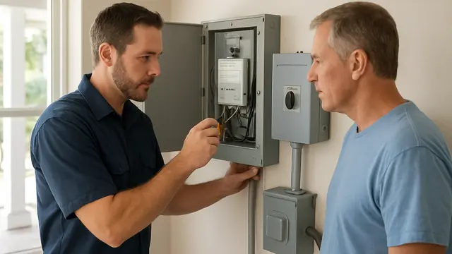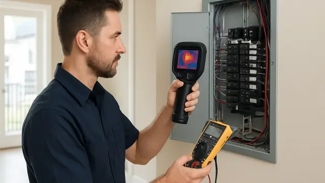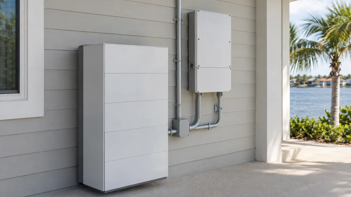
Do not remove an electrical panel cover, touch exposed conductors, bypass protection, or repeatedly reset a fault. Keep clear of smoke, sparks, burning odors, hot equipment, standing water near electricity, and downed lines, then call qualified help.
1. Define What Battery Backup Should Accomplish
Start with the consequences of losing electricity, not a battery model or the label “whole-home backup.” For a home along 30A in Walton County, success may look different during an occupied stay and a seasonal vacancy. Identify what would become unsafe, inaccessible, costly, or seriously disruptive without power. Rank those consequences before selecting equipment: protecting essential functions and preserving normal household convenience are different project goals.
Describe each outcome precisely. Refrigeration for groceries and temperature-controlled storage for medication carry different consequences if support ends. Communications may mean charging phones, keeping household network equipment operating, or supporting work calls; powering equipment inside the home cannot preserve an outside network that has failed. Accessibility may require continued use of equipment needed to reach a bedroom or bathroom. For sleep, distinguish preferred comfort from a health-related temperature requirement. These distinctions tell a designer which compromises are acceptable rather than treating every requested appliance as equally important.
Choose a primary planning horizon. Brief-interruption coverage aims to prevent a critical activity from stopping or requiring a disruptive restart. Overnight backup sustains selected functions between defined evening and morning times, with agreed limits on other uses. Extended-outage resilience addresses what happens when an outage outlasts the planned battery-supported period: whether essential service can be replenished, demand reduced, or occupants moved elsewhere. A system intended to bridge short interruptions should not automatically be treated as an overnight or multi-day solution.
Separate duration from interruption tolerance. A function may need support all night but tolerate a restart; another may be needed briefly yet cannot tolerate even a momentary loss of power. Record these as separate requirements. Chapter 3 addresses runtime estimates, Chapter 4 addresses equipment power demands, and Chapter 5 addresses transfer behavior. At this stage, define the outcome rather than choosing the technical means to achieve it.
Compare the property's occupancy states explicitly. During owner stays, occupants may be willing to defer cooking, laundry, or other ordinary uses to preserve higher priorities. During vacancy, no one may be available to make those decisions, and protecting essential property functions may matter more than comfort. In humid conditions, decide whether maintaining indoor conditions is a required outcome or merely desirable; a request to keep small devices running does not include humidity control. For guest stays, avoid making success depend on visitors understanding complicated restrictions. State the level of occupant cooperation the design may assume; detailed handoff arrangements belong in Chapter 16.
Correct two expectations before the project advances. “Whole-home backup” does not establish that every appliance can operate simultaneously or that every device will continue without interruption. A battery also has finite stored energy: it cannot provide indefinite service without replenishment, and a charging source does not by itself establish sustained operation. The project needs a defined service goal, not a promise that the home will behave normally through any outage. Charging feasibility is addressed in Chapter 6.
If loss of power could affect medical equipment or medically necessary storage, consult the equipment provider and, where appropriate, the treating clinician before selecting household backup. Establish permitted interruptions, approved alternative supplies, storage limits, and the response required if equipment alarms or support ends. A household battery should not be the sole continuity plan for a medically consequential outage. Equipment-specific backup, caregiver assistance, or relocation may be necessary according to that guidance.
Prepare a short owner requirements brief using the decisions below. Give the designer priorities to evaluate, not a self-selected battery size. Ask that conflicting objectives be identified before they become hidden compromises, for instance, whether preserving overnight comfort would shorten support for higher-priority functions. Define a fallback threshold tied to household needs, such as loss of accessible sleeping arrangements or inability to maintain required medical support, rather than waiting for the battery to be exhausted.
- Rank outcomes: distinguish nonnegotiable functions, important functions, and optional comforts, and state the consequence each priority prevents.
- Set service targets: give each essential function a desired operating period and an acceptable interruption, noting requirements that need provider confirmation.
- Identify occupancy assumptions: specify which priorities apply during owner stays, guest stays, and vacancy, and whether anyone can reasonably reduce ordinary consumption.
- Name acceptable compromises: list uses that may be deferred or unavailable and clarify whether limited comfort would satisfy the goal.
- State external dependencies: flag communications service, caregiver availability, access to another suitable location, and other needs household electricity alone cannot meet.
- Define success and fallback: request an assessment of supported outcomes against these targets, with unmet needs identified, and state when occupants should use an alternative arrangement.
2. Build an Essential-Load Inventory Without Opening Equipment
Build the inventory around equipment and household functions, not presumed circuits. Identify the refrigerator, communications equipment, lights, and specific plug-in devices that serve the priorities established in Chapter 1. Circuit assignments come later: selecting an appliance does not establish what else would receive backup power through its existing connection.
For each item, record its location, make, model, quantity, and intended use. Photograph an externally visible nameplate only if it is readable from a normal, accessible position. Copy listed voltage, amperage, watts, and frequency exactly, with their units. Do not remove covers, move heavy appliances, or reach behind equipment to locate a label. Mark inaccessible information as unknown; consult the model-specific user manual or manufacturer documentation instead.
Keep rated information separate from consumption information. A nameplate can describe rated input or a maximum condition rather than ordinary use. An annual energy label is a standardized estimate, while a power adapter’s output rating describes its output capability, not the connected device’s actual demand at the receptacle. Identify whether each figure comes from a label, manual, existing device report, or professional measurement. Preserve conflicting figures for review rather than selecting the lowest.
Classify operating patterns as continuous, cycling, or occasional. Continuous equipment remains active through the required period, although its demand may change. Cycling equipment automatically switches components on and off. Occasional equipment operates in user-selected sessions. Record standby operation separately when relevant: a device used occasionally may still draw power between sessions. These categories describe behavior, not priority; an occasional accessibility-related use may be more important than a continuously operating entertainment device.
Add the observations that make each category useful. For continuous equipment, note required availability and any scheduled shutdown. For cycling equipment, record automatic defrost, auxiliary heaters, or other functions identified in the manual, without trying to infer their consumption. For occasional uses, note typical session length, frequency, and whether use can wait. Identify devices likely to operate together. Tag observations by date, occupancy, and relevant conditions so the designer can select appropriate inputs for Chapter 3 rather than treating every observation as interchangeable.
Apply the project’s established priorities item by item: required, optional, or excluded. List each refrigerator and freezer separately. For lighting, identify the actual fixtures or portable lamps needed for selected activities rather than requesting an entire room. For receptacle uses, name the intended devices and quantities. An outlet requested for charging phones should not become an undefined allowance for any appliance a guest might connect. Record intended use restrictions for design review.
Do not assume nearby devices share a circuit, or that a room has only one circuit. A selected refrigerator may share a circuit with unwanted loads, while essential lights may span several circuits. Existing circuit labels are leads, not verified mapping. Flag uncertain connections; Chapter 5 addresses the choices for accommodating the verified circuit arrangement.
Identify every powered component supporting each desired function. Internet access may require a modem or optical network terminal, router, network switch, and separate Wi-Fi access points located throughout the home. Powering them does not ensure the provider’s outside network remains available. A remotely monitored sensor may also depend on a powered hub and that network connection. For equipment involving controls, pumps, or several connected units, list all known components and mark uncertain dependencies for professional review.
Save available utility interval data and existing consumer-facing energy reports. Preserve the reporting period, timestamps, interval length, units, and whether values represent energy per interval or average power. These records can reveal overnight baselines and recurring demand periods, but whole-home readings combine loads and do not establish individual circuit assignments. Interval averages can also hide brief peaks. If solar or storage already exists, check whether the report represents household consumption or only net electricity exchanged with the utility. Treat app-generated appliance estimates as estimates unless their measurement basis is established.
Have a licensed electrician turn the inventory into verified electrical information. The deliverable should connect selected equipment to actual circuits, identify shared loads and separately powered dependencies, and distinguish measured values from unresolved assumptions. Use the following questions to define that verification; runtime calculations and starting-power analysis follow in Chapters 3 and 4.
- Which circuits supply each selected appliance, fixture, receptacle, and supporting component, and what additional loads share them?
- What supply voltage, connection type, and other equipment requirements must the designer accommodate?
- Which label discrepancies or unknown model details require resolution before the equipment can be included?
- Which loads need professional measurement across standby, ordinary operation, automatic cycles, or simultaneous use, and over what observation period?
- Which motor-driven or variable-output equipment needs further starting-demand verification under Chapter 4?
3. Estimate Usable Energy and Realistic Runtime
Use the essential-load inventory from Chapter 2 to build an energy budget for the outage period. The useful comparison is energy available to household loads versus their accumulated consumption, not advertised battery size versus the sum of appliance nameplate ratings. Establish a no-recharge baseline so proposals can be compared without differing assumptions about energy recovered during the outage.
Kilowatt-hours, abbreviated kWh, measure energy: an average draw of 100 watts over ten hours consumes 1 kWh. Nominal capacity describes rated stored energy, some of which may be outside the battery's permitted operating range. Usable capacity is the better starting point, but its measurement boundary matters. A specification may describe usable direct-current energy at the battery or alternating-current energy delivered to loads. Compare capacities on the same basis and under stated test conditions.
For each steady load, multiply watts by operating hours and divide by 1,000 to obtain kWh. For cycling equipment, calculate consumption across its operating states. Compressor draw multiplied by estimated running hours captures only part of refrigerator consumption; standby operation and defrost also matter. Duty cycle, the fraction of time equipment runs, must reflect the modeled conditions rather than an assumed universal percentage. Variable-speed equipment may need measured energy data or an operating profile instead of a single running wattage. Where reliable daily energy measurements exist, they can be more useful than reconstructing consumption from nameplate values.
Daily totals alone can hide important timing differences. Lighting may cluster in the evening, while cooling demand can remain elevated after a hot day. A designer should use hourly or otherwise suitable time steps when demand changes substantially. At the same starting charge, an outage beginning just before an evening consumption peak may have a different runtime from one beginning afterward. The model should follow the intended load schedule rather than spread every appliance's daily consumption evenly over 24 hours.
Account for conversion losses and system overhead consistently. Converting battery energy to household alternating current incurs losses, and efficiency can vary with loading. Controls, communications hardware, and thermal management may also consume energy during backup. These demands can be a substantial part of the total when household loads are small, so halving appliance consumption may not double runtime. If a delivered-capacity figure already includes particular losses or overhead under its test conditions, do not subtract them again. Round-trip efficiency includes charging losses and should not automatically be used as the discharge-efficiency factor for an already charged battery.
Capacity accounting must identify the charge interval available during the outage. A protective discharge floor may already be excluded from stated usable capacity. A user-selected backup reserve may instead affect starting charge without remaining unavailable during backup. Do not subtract both automatically. Have the designer map displayed charge percentages to the proposed system's available energy and identify any additional energy held back during outage operation. Chapter 10 covers how operating modes and reserve settings establish that starting condition.
For approximately steady demand, runtime in hours equals available delivered energy in kWh divided by average consumption in kW, including overhead consistently. For changing demand, track cumulative energy use until the modeled discharge limit is reached. This calculation does not establish whether equipment can start or operate together; Chapter 4 owns those power-delivery checks.
Express uncertainty through distinct demand cases rather than one precise-looking number. Vary the inputs that matter: refrigerator cycling and door openings, occupancy schedules, and thermostat choices where cooling is included. Heat and humidity should inform those inputs, not serve as a generic runtime deduction. Identify whether the largest uncertainty comes from household demand, starting charge, or battery performance; better consumption data may resolve a sizing question more effectively than adding capacity.
Compare beginning-of-life performance with a later-life case using a stated retained-capacity assumption supported by product documentation. Age and use can reduce capacity, while operating temperature can affect available energy. Keep these effects distinct and avoid unsupported compounded deductions. A warranty capacity threshold is a contractual benchmark, not a prediction of exact capacity on a particular date. The decision is whether the later-life case still meets the required duration for the priority loads.
- Request no-recharge cases at full charge, anticipated everyday starting charge, and a lower plausible starting charge, within equipment-supported limits.
- At matching starting charges, compare minimum essential loads with the broader comfort-load package. Show the runtime gained by omitting optional loads.
- Include lower- and higher-demand conditions for both beginning-of-life and later-life capacity; avoid combining every favorable assumption into the headline estimate.
- Define each endpoint: reaching the discharge floor, shedding a load group, or losing a required household function. These are not interchangeable measures of runtime.
- Keep recharge-assisted estimates separate; Chapter 6 addresses solar recovery. Treat all estimated hours as conditional planning results, not guarantees.
4. Check Power Delivery and Equipment Starting Requirements
Chapter 3 addresses how long stored energy can last. This chapter checks whether the system can deliver power fast enough. Kilowatt-hours (kWh) measure energy; kilowatts (kW) measure its delivery rate. Enough energy for hours of operation does not establish that an inverter can start a compressor or support the desired appliances simultaneously.
Compare continuous AC output in backup operation, not an inverter’s grid-connected rating or a battery module’s discharge rating alone. The complete system is limited by both battery delivery and inverter capability. Temperature and state of charge can reduce available output. Additional battery modules may increase stored energy without increasing AC power when the inverter is already the limiting component. The relevant comparison is simultaneous running demand against output available under the proposed operating conditions.
Surge output is a temporary allowance whose duration matters as much as its size. A peak available for a fraction of a second may not support a motor that needs several seconds to accelerate. Specifications may express limits in watts, amperes, or volt-amperes; these are not interchangeable. Motor power factor and starting current can make current or apparent-power limits decisive even when running watts appear acceptable. The designer should compare the expected starting demand over time with the manufacturer’s documented overload capability.
Exceeding that capability can produce different outcomes: current limiting, voltage reduction, output shutdown, or an automatic recovery attempt. Voltage reduction may prevent a motor from accelerating, prolonging the starting demand rather than solving it. A shutdown may also interrupt unrelated backed-up loads. Establish whether an unsuccessful start disconnects all backup output, whether restart requires intervention, and how equipment-required restart delays are preserved. Repeated automatic attempts are not evidence of compatibility.
Motor evaluation should use exact equipment models and manufacturer information. Running current alone cannot establish starting demand. Locked-rotor amperage, where listed, helps characterize a conventional motor’s starting challenge but does not predict starting duration or compatibility by itself. Variable-speed equipment may have lower starting demand, yet its electronic drive still needs a compatible supply. Where documentation is insufficient, a licensed electrician or appropriately licensed equipment technician should determine whether starting-current and voltage measurements are needed. Homeowners can supply accessible labels, manuals, and observations without opening equipment.
The assessment must include the loads already operating when the motor starts and the conditions affecting acceleration. For air conditioning, count the indoor blower and controls as well as the outdoor unit; if heat-pump operation is included, address any enabled auxiliary electric heat separately. Cooling performance under hot, humid conditions should not be inferred from a mild-weather start. Manufacturer restart delays also matter after an interruption, particularly when multiple appliances could attempt to restart together.
Output configuration can disqualify a system despite adequate total wattage. Verify voltage, frequency, phase arrangement, and available current for each demanding load. A 240-volt appliance needs the appropriate supply. On a split-phase system, per-leg current limits and permitted imbalance can restrict the combination of 120-volt loads before the total output rating is reached. Voltage regulation and waveform requirements may also affect electronic controls or motor drives. These checks must apply during backup operation, without utility support.
Professionally designed sequencing can stagger starts or suspend a lower-priority load while cooling operates. It cannot solve a single motor’s excessive starting demand even with other loads removed, nor can staggering starts cure excessive combined running demand. Compatible starting assistance, such as a manufacturer-approved soft starter for a suitable compressor, may reduce starting current. It does not remove running demand, and suitability must be verified for the compressor, its controls, and the battery inverter. Selection and installation belong to licensed professionals; a generic soft-starter claim is insufficient for variable-speed equipment.
Before accepting a claim that the system supports air conditioning or another demanding load, evaluate the following technical evidence. Chapter 14 should verify the resulting approved criteria, not substitute a single successful start for this assessment.
- Model-specific manufacturer data or compatibility guidance for the battery, inverter, demanding equipment, and any starting assistance, not cooling tonnage alone.
- Running-load calculations that respect continuous output, current, per-leg limits, and applicable temperature and charge-level reductions.
- Starting-current and duration evidence compared with inverter surge limits, including concurrent loads and any relevant voltage-drop measurements.
- Defined sequencing priorities, restart delays, and the effect of unavailable load-management controls on supported operation.
- Explicit operating boundaries and unresolved uncertainties, with conditions requiring professional verification identified rather than represented as guaranteed performance.
5. Choose the Backup Architecture and Isolation Strategy
Backup architecture establishes the electrical boundary of backup service: which circuits can receive battery power, which remain outside that boundary, and which controls govern access. Choose that boundary using the load priorities and power checks from Chapters 2, 4. Here, “30A” refers to the community, not an assumed electrical service rating; the actual service arrangement must be verified.
A dedicated essential-load arrangement supplies selected circuits through a backed-up distribution section, often a separate panel. Excluded circuits cannot use battery power during an outage, even when capacity is available. This physical separation makes the arrangement comparatively easy to understand and limits accidental use of excluded loads. The selection is generally circuit-based, however: a circuit serving the refrigerator may also supply discretionary receptacles. Backing up that circuit does not reserve its power exclusively for refrigeration.
A whole-home connection places more of the home's distribution within the backup boundary, while managed limits determine which loads may operate. Its practical advantage is access: more lighting and receptacle circuits can remain available without relocating every selected circuit. Its constraint is dependence on effective load control. Compare proposals by which loads are unrestricted, which are automatically shed, and which depend on occupant restraint, not by the whole-home label. A warning notification is not automatic load enforcement.
The choice is not strictly binary. A design can combine a dedicated backup section with controls on selected loads inside it. This can preserve a clear boundary while allowing a demanding load to operate only when conditions permit. Ask whether that added flexibility serves an actual household priority or merely adds equipment and troubleshooting dependencies.
Approved isolation or transfer equipment disconnects the backed-up section from the utility supply so the battery can serve it without energizing utility lines. The isolation function may be integrated into system equipment or provided by a separate compatible device; its location defines the backup boundary. Utility restoration follows the system's designed reconnection sequence. A battery inverter or a non-export setting alone should not be assumed to provide outage isolation. Solar operation within that boundary is addressed in Chapter 6.
Automatic transfer can still interrupt power. Sensitive electronics may reboot or lose work even when most household loads appear unaffected. Compare the manufacturer's transfer specification for the exact configuration with the interruption tolerance of the equipment being protected, including the return to utility service. An equipment-level uninterruptible power supply may bridge those gaps. Its power rating, bridge duration, and acceptance of the battery-backed supply need checking; an existing UPS is not automatically compatible simply because both products provide backup.
Relocating circuits creates a durable physical selection but can involve substantial electrical reconfiguration. A licensed electrician must evaluate circuit routing, shared neutrals, panel capacity, and whether separating essential from discretionary uses requires additional circuit work. Compatible load-management devices may avoid some relocation and allow adjustable priorities, but introduce sensors, controllers, switching devices, and configuration dependencies. Distinguish circuit disconnection from commands sent to compatible appliances: they affect equipment differently and do not necessarily provide equivalent control.
For a managed arrangement, the useful comparison is the complete control sequence. Identify what triggers shedding, whether control responds quickly enough for the proposed loads, and how reconnection is delayed or staggered. Specify what happens if a sensor, controller, or control link fails. A priority list without failure behavior leaves a central architecture question unanswered: does the system preserve essential service, admit excess demand, or stop supplying backup?
Compatibility review must cover the existing service equipment, ratings, grounding and neutral arrangements, transfer location, and exact battery, inverter, isolation, and load-control components. Existing generators or other power sources can require mutually exclusive operation or additional coordination; independent compatibility with the home does not establish compatibility with each other. The design should identify permitted source combinations and prevent prohibited ones, leaving solar charging details to Chapter 6.
Use a homeowner-readable architecture drawing tied to the professional electrical diagram. It should show the utility connection, isolation boundary, backed-up distribution, excluded circuits, controlled loads, and other sources. An accompanying operating-state table should answer the following questions without requiring the owner to interpret wiring details.
- Utility available: Which circuits receive normal service, and do any controls restrict everyday use?
- Outage: Which circuits remain eligible, which are excluded, and which are automatically controlled?
- Restricted operation: What is shed first, and what conditions permit each controlled load to return?
- Battery shutdown or control failure: Which circuits lose supply, and is recovery automatic or dependent on authorized service?
- Other sources: Which source combinations are permitted, and which must remain separated?
- Utility restoration: How are transfer and load restoration sequenced, and where can another interruption occur?
6. Decide Whether and How Solar Will Recharge the Battery
A utility-charged battery-only system cannot replace energy used during an outage unless another designed charging source is available. Solar-plus-storage can supply daytime loads and replenish storage, but only when the solar equipment supports outage operation and production exceeds concurrent demand. Decide whether solar recharge is necessary for the outage duration established in Chapter 1; adding panels does not by itself provide extended-outage resilience.
Ordinary grid-connected rooftop solar generally shuts down when utility power disappears. Its grid-following inverter needs an established electrical reference and must not energize a failed utility connection. A backup-capable system can create a local grid for compatible solar equipment within the isolation boundary described in Chapter 5. Solar located outside that boundary may remain unavailable even while the battery powers household loads. The key question is whether the proposed array can supply loads and charge storage with the utility absent, not merely whether solar and batteries operate together normally.
AC-coupled storage connects separate solar and battery inverters on the alternating-current side. This can preserve a functioning solar installation, making it attractive for retrofits. Storing solar energy generally involves conversion from panel DC to AC and then back to DC, with losses at each step. More importantly, retaining an inverter is useful only if it can operate within the battery-created island and respond to supported production controls. Compare retrofit options by retained equipment, islanded compatibility, charging efficiency, and limits on solar inverter capacity relative to the battery system.
DC-coupled storage connects solar and batteries through a coordinated DC-side arrangement, often with a hybrid inverter. It can reduce conversion steps for stored solar energy and, in some designs, capture production that would otherwise be clipped by the inverter's AC output limit. An existing solar installation may require inverter replacement or substantial reconfiguration. For new solar, integration may be simpler, but shared conversion equipment creates limits that must be evaluated for simultaneous load supply and charging. Neither arrangement makes panels, batteries, and controls universally interchangeable.
For solar planned later, assess what the initial battery equipment actually supports. A solar-ready label does not establish a supported future array size, coupling method, or outage capability. Determine whether expansion would require another inverter, additional controls, or changes to the backup boundary. Existing production history can inform recharge estimates, but it cannot establish electrical compatibility.
While islanded, generation and battery discharge must balance household consumption, battery charging, and losses. When solar output exceeds demand and available charging capacity, the system must curtail production, deliberately reduce it. Supported controls may use direct communications or changes in the local electrical frequency. Some combinations smoothly reduce output; others stop solar and reconnect it after a delay. The designer should explain the proposed equipment's behavior when the battery is full, clouds pass, or a large load switches off. Reconnection delays and minimum operating thresholds can reduce harvest even on a sunny day.
Low-charge recovery is a separate compatibility requirement. After a protective shutdown, the system may lack the energy needed to establish the local AC grid that an AC-coupled solar inverter requires. Black start means initiating operation without an already energized AC supply; it is not a universal battery feature. Some systems retain restart energy or can start from sufficient solar input, while others need utility restoration or qualified service under particular conditions. Ask which shutdowns allow automatic solar recovery, what sunlight and battery conditions are required, and whether loads remain disconnected until adequate charge returns. Sunrise alone is not proof of recovery.
Recharge estimates should model the proposed array and backed-up loads together over time, not substitute annual solar yield or panel nameplate capacity for available charging energy. Use the Chapter 3 load assumptions and starting charge. Seasonal daylight, orientation, shading, cloud cover, and temperature affect production; storm-related cloud cover can coincide with an outage. Concurrent consumption, conversion losses, battery charge-acceptance limits, and inverter limits determine what actually reaches storage. Show charge trajectories across successive days, including any load reductions needed to avoid shutdown.
- Compatibility: Do the exact inverter, battery, and control models support islanded operation together, with the proposed firmware, solar capacity, and charging limits?
- Power allocation: What solar power can serve loads and charge storage simultaneously? Identify shared inverter limits and any restrictions at high or low battery charge.
- Recovery: What happens after low-charge shutdown versus a fault, and which conditions prevent automatic restart?
- Recharge cases: Compare a seasonal clear day, a cloudy day, and consecutive low-production days. State shading and consumption assumptions, expected end-of-day charge, and any periods with no net charging rather than promise daily full recovery.
7. Evaluate Coastal Installation Locations
Compare candidate locations against the proposed equipment’s installation instructions, not simply proximity to electrical equipment. For a 30A home, heat, humidity, storms, and salt exposure can affect siting, but neither an exterior wall nor a garage is automatically the better choice. Evaluate the complete equipment grouping, including associated controls and power-conversion equipment, rather than the battery cabinet alone.
From normally accessible areas, photograph each candidate location with enough surrounding context to show doors, windows, existing equipment, parking, and walking routes. Record approximate unobstructed width and height, available floor depth, and nearby obstructions where safely measurable. Note the time of day when observing sunlight; one shaded photograph does not establish all-day shade. Do not move equipment, remove covers, enter restricted spaces, or enter standing water for measurements. Leave inaccessible dimensions unverified.
Compare temperature limits with performance conditions. A product may be permitted to operate at a temperature where charging or output is reduced; prolonged heat can also affect service life. Garages can retain heat, while exterior walls may receive intense afternoon sun. Ask the designer to assess expected conditions at the equipment, including heat from nearby equipment and restricted airflow. Any proposed shade structure or enclosure must preserve manufacturer-required cooling and access space.
Treat humidity, condensation, and salt exposure as separate checks. Determine whether the manufacturer’s humidity limits require noncondensing conditions and whether the product is suitable for the expected corrosion exposure. An outdoor enclosure rating addresses specified exposure to water and solids; it does not by itself establish resistance to salt corrosion, persistent condensation, or flood submersion. Review environmental suitability for mounting hardware and associated components as well as the battery. Indoor placement can reduce direct weather exposure without eliminating humid or salt-laden air entering through garage doors.
Document visible water pathways: staining, past water marks, downspout discharge, irrigation spray, low spots, and openings exposed to wind-driven rain. Share known storm and water-intrusion history. These observations help frame a professional assessment; an address, neighborhood reputation, or apparently elevated floor cannot establish acceptable flood exposure. The assessment should use relevant flood information, site elevations where needed, drainage conditions, and the vulnerability of all required system components.
Ask whether runoff can collect at the proposed base, water can enter through nearby openings, or indoor leaks could reach equipment. Raising the battery is not a complete answer if associated components remain vulnerable. Elevated mounting can also change anchorage, structural loading, access, and replacement logistics. Any drainage changes or building modifications needed to make a location suitable should be identified before accepting that location.
A wall’s finish does not establish its capacity to support a battery. The designer should identify supporting construction, installed equipment weight, mounting geometry, anchor requirements, and the load path into the building. Uncertain framing, deteriorated materials, questionable masonry, multiple units, or elevated supports may require qualified structural review. Floor-mounted equipment also needs a suitable supporting surface. Structural access, mounting, and installation belong to licensed professionals; homeowner photographs cannot verify concealed support.
Test the layout against ordinary use, not an unusually empty room. In a garage, account for parked vehicles, door swings, storage, and pedestrian routes. Ask whether vehicle-impact protection is needed and whether it would compromise service access. Outside, consider gates, landscaping growth, outdoor showers, irrigation, and routes used for bins or beach equipment. Include access for removing and replacing a unit, not just reaching its controls.
Compare model-specific sound information where bedrooms, patios, or neighboring occupied spaces are nearby. Ask when fans or other audible equipment operate, particularly during hot conditions. Judge appearance using the full equipment grouping and visible connection routes. Screening must preserve airflow and service access. Resolve safety separations under Chapter 8 and exterior approval requirements under Chapter 9 rather than treating visual acceptability as installation approval.
Before selecting the location, use an annotated, dimensioned site assessment to compare the viable alternatives. It should distinguish verified conditions from assumptions and resolve these placement questions:
- Do the exact proposed models’ temperature, humidity, condensation, and corrosion limits suit the expected exposure, including direct sun and retained heat?
- What site-specific flood, runoff, rain-entry, or leak concerns remain, and does suitability depend on further evaluation or site work?
- Can the supporting construction carry the installed equipment with the specified mounting and anchorage, or is structural review still required?
- Does the layout show manufacturer-required clearances for each component, cooling space, service and replacement access, door movement, and normal household circulation?
- Can any required impact protection, shading, or screening fit without creating new access or cooling conflicts? Keep a location provisional while a condition that determines its suitability remains unresolved.
8. Evaluate Battery Safety and Emergency Information
Compare battery safety at the system level, not by chemistry label alone. Lithium iron phosphate generally has greater thermal stability than some other lithium-ion chemistries, but it can still fail, vent hazardous gases, and burn. Other chemistries have different failure characteristics and protective needs. Ask how the proposed system detects and responds to overheating, overcharging, and electrical faults, and what limits fire propagation between cells or modules. Chemistry, enclosure design, protective controls, and installation arrangement all matter; “fireproof” is not a credible selection criterion.
Certification of individual cells, modules, or inverters does not establish that their assembled combination is an evaluated energy storage system. Request evidence covering the proposed system and its permitted component combinations. UL 9540 addresses energy storage systems and equipment; UL 9540A is a test method for evaluating thermal runaway fire propagation, not an interchangeable system certification. When a proposal relies on fire testing, ask which models, unit quantities, spacing, and installation conditions the results support. Testing does not establish that a fire cannot occur.
Before placement is finalized, the licensed installer must resolve the fire-safety questions below with the applicable building and fire authorities and manufacturer instructions. Chapter 7 addresses environmental and structural siting; this review concerns fire exposure, escape, detection, and responder access. A layout that relies on a particular tested arrangement must retain those conditions; changing a model, unit count, or spacing can require renewed safety review.
Recognize warning signs only from normally accessible areas. An unusual chemical or burning odor, smoke, hissing or popping, swelling or deformation, or abnormal heat apparent without touching calls for withdrawal, not investigation. Do not approach to identify an odor, feel the enclosure, open a cover, or operate nearby controls. For smoke, suspected venting or fire, or other immediate danger, leave the affected area and call 911 from a safe location. Tell dispatch that a stationary home battery is involved. Keep others away, avoid smoke and vapors, and do not attempt suppression or reenter because smoke has stopped; dangerous conditions or reignition may remain.
Keep a short emergency information sheet somewhere occupants can reach without approaching the battery, including an offline paper copy. It should give the property address, equipment location, manufacturer and model, and the presence of solar or other connected power sources. Make the response distinction explicit: call 911 for suspected fire or immediate danger; use the installer’s or manufacturer’s service contact for non-emergency faults. State that occupants should avoid the equipment and follow responders’ instructions. Identify where the approved shutdown instructions and system diagram can be found without turning the sheet into a homemade electrical procedure.
Have the installer explain what approved shutdown controls do and do not isolate, who may operate them, and under what conditions. A disconnect does not eliminate energy stored inside battery cells, and other connected sources may remain energized. Emergency instructions must never direct occupants through smoke, heat, standing water, or damaged areas to reach a control. Providing responders with the equipment information is more important than attempting a shutdown that requires approaching danger.
Submerged, impacted, or visibly damaged battery equipment must remain untouched even if it is silent or its display appears normal. Water intrusion and mechanical damage can cause concealed electrical faults, compromised cells, and delayed fire hazards. Do not dry, move, recharge, restart, or reconnect it, and do not enter standing water to inspect it. Report immediate danger to emergency services; otherwise contact the installer or manufacturer’s qualified service channel from a safe location. Keep the equipment out of use pending emergency or qualified professional direction.
- Separation and grouping: What separation is required from doors, windows, escape routes, combustible materials, and other equipment? What limits apply to the number and arrangement of battery units?
- Protective construction: Does the proposed location require a fire-resistant enclosure, barrier, or other protective construction? What system evaluation or installation instruction supports that arrangement?
- Detection: What smoke, heat, or other detection is required for this equipment and location? Do existing household alarms satisfy those requirements, or is additional detection necessary?
- Emergency access: Can occupants leave without passing the equipment, and can responders identify and access it? What labels, access provisions, and approved shutdown information must be available? Required clearances must remain free of storage or other obstructions.
9. Confirm Utility, Permit, Association, and Insurance Requirements
Establish the approval path for the specific property before committing to equipment or placement. A 30A address does not by itself establish the serving utility, permitting jurisdiction, association restrictions, or insurance conditions. These reviews are separate: utility acceptance does not replace a permit, association consent does not establish electrical compliance, and inspection approval does not determine insurance coverage.
Use the service address and current electric bill to identify the utility. If a billing intermediary appears, confirm which organization operates the distribution connection and handles interconnection. With the parcel identification and official jurisdiction records, have the installer verify the permitting authority. Ask that office which additional reviews apply to the proposed scope, including any fire or structural review. A neighboring property's approval route is not sufficient evidence.
The utility inquiry must describe the proposed configuration, not simply call it backup-only: battery-only or solar-plus-storage, existing or new solar, inverter models and ratings, grid-parallel capability, and intended export behavior. The installer should provide the technical drawings needed for review. Ask whether storage requires a new application or amendment to an existing solar agreement, whether grid charging affects eligibility or operating conditions, and whether export rules distinguish solar production from stored energy.
Non-export capability does not establish an exemption from interconnection review. Ask whether the utility accepts the proposed export-control method, where any export limit is measured, and what evidence is required to verify compliance. Resolve these conditions before treating the selected equipment as acceptable. This chapter concerns authorization; the underlying isolation and solar architecture belong in Chapters 5 and 6.
Clarify the utility's sequence for application review, installation, inspection, controlled commissioning, and any required permission to operate. In particular, determine whether testing is allowed before final authorization and under what restrictions. A submitted application or passed electrical inspection is not permission to operate when separate utility authorization is required. The schedule must distinguish permission to construct from permission to run the proposed configuration.
Use one project responsibility matrix, incorporated into the contract, rather than separate overlapping task lists. For the approvals covered here, assign permit preparation and submission, responses to review comments, inspection scheduling, deficiency correction, permit closure, utility applications, association submissions, and insurer notification. Identify both the responsible party and the dependency for each task. Clarify which application and review fees are included; carry their budget treatment into Chapter 11 and broader contract terms into Chapter 12. The matrix should remain the shared reference during installation, with final approval evidence checked at handover in Chapter 14.
Review recorded restrictions and association procedures before settling an exterior layout. Obtain the governing documents rather than relying on a neighbor's recollection. Determine whether review covers batteries, associated electrical equipment, conduit routes, screening, or visibility from common areas, and identify submission requirements and meeting schedules that could affect timing. Association-requested screening must be reconciled with the siting requirements in Chapter 7; it should not become a separate, incompatible layout. If a restriction appears to conflict with applicable law, seek qualified legal guidance.
Notify the insurer or authorized agent that the project involves a permanently installed battery. Describe the proposed equipment, capacity, location, solar connection, and intended property use, including seasonal vacancy or rental occupancy. Ask what project information and completion evidence the insurer needs, whether notification is required before installation, and whether an endorsement or revised insured value is necessary. Request clarification of applicable limits, deductibles, and exclusions: acceptance of the installation does not establish coverage for equipment breakdown, storm damage, or rental-income interruption.
Maintain a single approval tracker linked to the responsibility matrix. Record submission dates, status, unresolved conditions, next actions, and the design revision each decision covers. Separate preliminary comments from actual approvals. Before procurement or scheduling, use these gates:
- Jurisdiction gate: Have the utility and applicable reviewing authorities been confirmed for the property, with any disputed responsibility resolved?
- Design gate: Do utility operating conditions, permit review requirements, and association placement conditions refer to a compatible configuration and location?
- Procurement gate: Which reviews must finish before equipment can be ordered confidently? If an early order is proposed, has the owner accepted the contract's allocation of cancellation, restocking, redesign, and delay exposure?
- Scheduling gate: Are review deadlines, inspection dependencies, and insurer-required actions reflected in the schedule rather than treated as parallel tasks that can always finish later?
- Revision gate: Has the responsible reviewer determined whether an equipment substitution, location change, or operating-mode change requires renewed approval?
- Operation gate: Who will confirm that outstanding conditions are closed and any required utility authorization has been received before unrestricted operation?
10. Understand Operating Modes, Reserves, and Connectivity
Choose operating settings by deciding when the battery should spend stored energy and when it should retain it. Have the installer demonstrate the proposed equipment’s actual controls: similar mode names can conceal different charging permissions, scheduling rules, and automatic overrides.
Backup-only mode generally prioritizes retaining charge for outages rather than supplying routine household demand while utility power is available. Manufacturer-controlled maintenance or calibration may still occur. Check the target charge level and which permitted sources replenish the battery; selecting this mode does not itself enable grid charging.
Self-consumption mode generally stores surplus solar production for later household use, reducing utility imports subject to the selected reserve. Rate-based mode instead schedules charging and discharging around electricity prices or tariff periods; approved configurations may also allow grid charging or exports. Ask whether tariff periods are entered manually, updated automatically, or supplied through an external service, and who must correct them when the tariff changes. Compare financial value in Chapter 11 rather than assuming either mode produces savings.
The backup reserve controls how much charge routine operation seeks to retain for an unexpected outage. A higher setting reduces energy available for everyday use; a lower setting allows more routine discharge but accepts a smaller starting buffer if power fails. Use Chapter 3’s capacity and runtime assessment to choose that tradeoff. Ask how the selected reserve affects each available mode and whether any third-party dispatch program can override it.
Changing the reserve is not the same as charging the battery. If current charge is below a newly raised reserve, recovery requires an available, permitted charging source and sufficient time. Check whether raising the setting initiates charging or merely prevents further routine discharge. Learn to distinguish current state of charge, the reserve preference, and actual charging status, including whether a remotely requested change has reached the equipment.
Weather-responsive charging can temporarily raise retained charge or request charging after a qualifying alert. Evaluate the alert source, geographic coverage, enrollment requirements, target charge, and conditions for returning to ordinary settings. Ask whether the feature requires internet access or an active subscription, and what happens if communications fail after an alert starts. Forecasts may arrive too late or miss an event; utility supply, solar production, or charging capacity may be insufficient to reach the target. Treat storm automation as a supplement, and check actual charge rather than relying on an enabled feature badge.
Evaluate loss of home internet, a cloud-platform outage, and subscription expiration separately. Require product-specific answers about local outage detection, utility isolation, battery protection, backup delivery, and any essential load-management controls. Determine whether reserves and schedules remain stored locally, whether optimization reverts to a fixed mode, and whether approved local viewing or user control requires cloud authentication. A battery may continue local backup while its app shows stale information; a reachable app likewise does not prove that backed-up loads are operating. Review displayed timestamps and the system’s available offline status indicators.
Before commissioning, establish an owner-controlled account with unique credentials, multifactor authentication where supported, and a usable account-recovery method. Separate read-only monitoring from permission to change settings. Review installer, service-provider, and energy-program access: can they change reserves, dispatch energy, update firmware, or download household usage records? Check how permissions are revoked, which access is required for support, and whether optional data sharing can be declined without losing core functions. Review what data is collected, who receives it, and available retention or deletion choices; detailed energy records can reveal household routines.
Routine homeowner controls may include mode selection, reserve, notifications, and supported tariff schedules, but only where designated as user settings by the manufacturer. Utility protection, export limits, inverter configuration, equipment pairing, and electrical load-management assignments remain with authorized licensed professionals. An app-visible parameter or accessible service menu is not permission to alter protected configuration.
- Identify command priority when a reserve preference, rate schedule, weather event, and third-party dispatch request conflict.
- Check whether temporary overrides expire automatically, and whether a restart or communications recovery restores the intended mode.
- Distinguish an app-saved request from equipment acknowledgment; find where pending or failed setting changes appear.
- Determine whether connectivity-loss alerts use an independent communication path. Notifications relying on the failed connection may not arrive.
- Identify an approved way to restore ordinary user preferences without resetting protected equipment configuration.
11. Assess Costs and Value Without Assuming Savings
Build one owner budget that separates project cost, resilience value, and utility-bill savings. Start with the gross cost before incentives, then show verified benefits and when they would be received. Compare alternatives over the same ownership period and against the same backup objectives from Chapter 1. A project can be worthwhile for resilience without paying for itself through electricity savings; that is a spending decision, not a failed savings calculation.
Separate upfront costs into equipment; design and site assessment; site preparation; electrical integration; approvals; commissioning and owner orientation; and optional monitoring setup. Equipment includes batteries, inverters, isolation equipment, and load controls. Site preparation includes mounting support, foundations, and restoration. Electrical integration includes wiring, circuit relocation, service-equipment changes, and existing-solar integration. Identify taxes, delivery, and financing fees separately or show where they are included. Use these categories across alternatives so a low equipment price does not obscure a higher installed cost.
For each category, distinguish priced work from allowances and unresolved costs. Carry unresolved site conditions as a budget exposure rather than zero, using a contingency tied to identified uncertainties instead of an arbitrary percentage. Separate work necessary for the selected backup objective from spending driven by appearance, location preferences, or expansion provisions. Include interest and fees in financed comparisons, but do not count both loan principal and the full purchase price as separate costs.
Evaluate resilience on its own scorecard. Identify which consequences the proposed system can actually reduce, then distinguish reasonably estimable losses, such as refrigerated food, from personal benefits such as less disruption to sleep or an occupied stay. For a seasonally occupied home, value may depend on whether someone is present or able to respond. If assigning monetary benefits, state outage frequency, duration, occupancy, and system availability assumptions. Include a low-benefit case; past outages are not a forecast. Ask whether the purchase remains acceptable with no utility-bill savings.
Before estimating savings, obtain the serving utility's current tariff for the actual account, including its effective date and any rate change required for the proposed operation. Verify time-of-use periods, seasonal energy prices, applicable riders, demand-charge measurement rules, fixed charges, minimum bills, and export-credit rates and settlement rules. Confirm any tariff restrictions on charging from the grid or exporting stored energy. Use account bills and interval data where available rather than an annual average price.
Compare the marginal cost of charging with the charges actually avoided during discharge. Grid charging must account for all purchased charging energy, including losses. Solar charging must account for export credits forgone, where applicable. Model the operating reserve selected in Chapter 10 rather than assuming all capacity earns daily savings. Do not claim demand-charge savings without modeling the relevant billing peak, or savings on fixed charges that remain payable. Show sensitivity to rate changes, battery degradation, and operating patterns. Keep any utility-program payment separate and account for its dispatch obligations and effect on backup availability.
Check incentives through current information from the administering government agency, utility, or program administrator, and date the assumptions. Verify equipment and expenditure eligibility, ownership and property-use restrictions, application deadlines, installation or in-service dates, available funding, and rules for combining benefits. Distinguish a rebate from a tax credit or ongoing performance payment: their timing and usability differ. Obtain qualified tax advice where relevant, especially for rental or mixed-use property. Show unverified incentives only as a conditional scenario, not as a reduction in the base budget.
Compare long-term costs using consistent inflation and financing assumptions; if discounting future cash flows, disclose the rate. Include subscriptions, required service, charging losses, insurer-confirmed premium changes, and out-of-coverage labor and parts. Avoid counting losses again if already included in the bill model. Budget separately for possible battery, inverter, and control replacement, plus qualified removal, transport, recycling, and replacement integration. Use cost ranges and timing scenarios rather than treating warranty length as an exact replacement date. Chapter 15 addresses replacement logistics.
- Staged installation: Does the first stage deliver useful backup independently? Compare its lower initial commitment with repeated design, mobilization, approval, integration, and commissioning costs, plus the period spent without the deferred capability.
- Future expansion: Price enabling provisions separately. Assess supported capacity limits and electrical, software, and product-generation compatibility; spare space is not enough. Include a case in which expansion requires replacing existing components.
- Larger initial purchase: Compare credible avoided future work with financing cost, unused capacity aging, and the risk that needs change. Evaluate added capacity against the energy and power criteria in Chapters 3 and 4.
- Decision table: For each option, show upfront cash, incentive timing, recurring costs, replacement range, verified-rate savings, and resilience benefit. Keep speculative compatibility and unconfirmed incentives outside the base case.
12. Compare Proposals, Warranties, and Service Responsibility
Compare bids against the same owner requirements, load inventory, and site assessment. Require each bidder to complete the specification sheet below for the actual proposed configuration, not a product family. Mark unresolved items as pending. A lower total may reflect omitted integration work, fewer supported loads, or narrower service coverage rather than a better price.
Separate fixed scope, exclusions, allowances, and options. For each allowance, identify the assumed quantity, included labor, basis for final pricing, supporting cost records, and treatment of unused funds. Name who supplies excluded but necessary work. Use Chapter 11’s ownership-cost framework rather than comparing equipment totals alone.
Establish one contract responsibility matrix covering design, approvals, site preparation, electrical and solar integration, commissioning, finish restoration, and ongoing service. Identify the accountable company, its subcontractors where known, and the completion evidence for each assignment. Carry this matrix through installation and acceptance rather than creating competing responsibility lists. Reference Chapter 9’s approval dependencies and Chapter 14’s handover checklist in the contract.
Set the change-order and substitution rules here. List foreseeable price or schedule triggers, distinguish them from already included work, and require owner approval of scope, price, and schedule effects before additional work proceeds, except for narrowly defined emergency protective actions. Equipment substitutions need exact model identification and disclosure of effects on compatibility, performance, footprint, warranty, and support. A supplier shortage should not automatically authorize an unspecified equivalent.
Compare actual warranty documents for every proposed model. Product coverage addresses specified equipment defects; workmanship coverage addresses installation defects. Record each provider, start date, term, claim deadline, and remedy. Determine who pays diagnosis, travel, labor, shipping, removal, and reinstallation, including when a manufacturer supplies a replacement part but no labor. Check whether replacements may be refurbished, whether coverage lasts only for the remaining original term, and what happens if the model is discontinued.
Assess retained-capacity protection separately from defect coverage. Record the warranted capacity threshold, its reference capacity, test conditions, who performs and pays for testing, and the remedy for a qualifying shortfall. This is not a household-runtime guarantee. Identify whether coverage ends at the earlier of elapsed time, cycles, or energy throughput, and how throughput is counted. Compare those limits against the operating mode selected in Chapter 10; a long calendar term may offer less protection under frequent cycling.
Review registration deadlines, required maintenance, connectivity obligations, permitted operating modes, and environmental exclusions. For the proposed coastal location, have the bidder identify any warranty restrictions involving salt exposure, corrosion, or water damage and reconcile them with Chapter 7’s site assessment. Seek clarification of ambiguous terms from the warranty issuer, not merely a sales representative. Check transferability, transfer fees, and registration requirements if the property may be sold.
Name one first contact for system faults, even when different companies supply the battery, inverter, controls, and installation. The service terms should assign triage, professional diagnosis, manufacturer claims, and coordination when suppliers disagree about the cause. Establish diagnostic charges and whether they are credited if a covered defect is confirmed. Distinguish acknowledgment, visit scheduling, and repair targets; none alone promises restored backup. Compare travel charges, after-hours availability, parts availability, and the route to support if the installer closes or loses manufacturer authorization.
Verify the contracting entity and appropriate license scope through the official licensing source. Request current insurance evidence and confirm relevant coverage with the insurer or agent. Verify manufacturer installation and warranty-service qualifications separately from sales authorization. Seek references for comparable architecture and integration complexity, asking specifically how faults and warranty claims were handled.
Tie payments to verifiable milestones, with deposit, equipment delivery, completion, and acceptance obligations clearly defined. State equipment ownership and refund treatment if procurement or installation is canceled or delayed. Make Chapter 14’s acceptance criteria and required records contractual deliverables. Define deficiency notices, correction periods, escalation contacts, and dispute procedures, including mediation or arbitration provisions where proposed. Review terms that limit remedies or shift dispute costs before signing.
- Equipment: exact battery, inverter, transfer equipment, and controller models; module quantities; load-management devices; required accessories.
- Performance: usable capacity and its measurement basis; continuous output; surge magnitude and duration; applicable temperature, charge-level, and configuration conditions.
- Architecture: selected backup arrangement, included and excluded loads, load-control assumptions, and solar integration boundaries, referencing the approved design.
- Commercial scope: included work, exclusions, allowances, owner-supplied items, separately priced options, schedule assumptions, and the shared responsibility matrix.
- Protection and support: warranty documents, workmanship terms, uncovered service charges, named first contact, and escalation route.
13. Prepare the Property and Coordinate Professional Installation
Hold a preconstruction meeting with the installer’s project lead, affected trades, and the owner or authorized representative before delivery. Work from the approved design and signed scope. Use the project responsibility matrix established during contracting rather than creating a separate set of assignments. This meeting should turn those commitments into a workable sequence: who arrives when, which spaces become unavailable, what must be completed before the next trade starts, and who can resolve a field question.
Confirm equipment positions, routing areas, mounting work, and temporary work boundaries against the approved layout. Permanent equipment clearances do not describe all the space crews need for lifting and staging. Identify protected surfaces, permitted entry areas, and household routes that must remain usable. Ask whether electrical, structural, weather-sealing, and finish work require separate visits, and whether any interval between them would leave a room, doorway, or exterior area unavailable. Confirm the field lead, owner decision-maker, alternate contact, and response method for time-sensitive questions.
Have the licensed electrician identify the expected extent, number, and duration of electrical interruptions, including uncertainty in restoration time. Installation work can interrupt loads outside the eventual backup arrangement, and the new battery should not be assumed available during connection work. Agree on advance notice, notification immediately before shutdown, and an update if restoration slips. Occupants also need clear notice when normal use can resume; a scheduled end time is not confirmation that work is complete.
Choose interruption windows around refrigeration, remote work, powered accessibility equipment, and occupied stays. Keep refrigerator and freezer doors closed, and have a food-handling plan based on authoritative food-safety guidance if the interruption extends. Move time-critical computer work or calls elsewhere rather than relying on the estimated restoration time. Arrange accessible alternatives before powered access equipment becomes unavailable. Use the separate medical-equipment continuity plan where applicable. If an occupied stay cannot tolerate uncertain restoration, rescheduling installation is preferable to promising an exact outage duration.
Review accessible delivery routes with the project lead, noting gates, steps, narrow turns, soft ground, overhead obstructions, and vulnerable finishes. The contractor must verify the handling method and route for the equipment’s weight. Agree on parking and unloading space that preserves emergency access and does not trap occupants’ vehicles. Coordinate shared driveways or other shared-access areas before delivery. Establish controlled entry, pet separation, restroom arrangements, and end-of-day locking. Homeowners should clear only agreed household belongings, not move equipment or create structural access.
Assign delivery receipt, shipping-damage assessment, and equipment custody to the contractor. Storage must meet manufacturer conditions and remain secure without blocking household access. Compare delivery timing with the construction sequence: early arrival provides scheduling flexibility but adds storage exposure; arrival immediately before installation reduces storage time but makes delivery delays more disruptive. For exterior work, establish who postpones activity during storms or wet conditions, who informs occupants, and how materials and unfinished openings will be protected.
Use the existing responsibility matrix to resolve trade interfaces before work starts. For each penetration or disturbed surface, identify the appropriately licensed trade responsible for opening it, restoring weather protection, repairing finishes, and completing any structural work. Confirm the sequence where one trade’s work will conceal another’s, including who checks weather protection before closure. Do not treat surface caulk as a universal solution for exterior penetrations. Settle temporary protection between visits and the limits of painting, trim repair, landscaping restoration, and debris removal.
Apply the change-order procedure established in Chapter 12 when concealed deterioration, obstructions, or mismatched existing equipment invalidate the planned work. Pause the affected portion while the responsible professional assesses options. The owner should receive the condition, proposed response, and cost, schedule, and design implications before authorizing additional work. Define who may approve immediate protective measures if the owner cannot be reached; that authority should not become permission for an unreviewed redesign.
Capture construction evidence while it is still available. Ask the contractor for dated, location-labeled photographs of concealed routes, mounting details, penetrations, and weather protection before closure, linked to any approved revision. Add these to the existing project record for the Chapter 14 handover rather than maintaining a duplicate checklist. Homeowners can document accessible finishes before work and visible impacts from outside work boundaries. Before crews leave, obtain a status update covering secured access, temporary protection, remaining restrictions, and the next visit.
14. Verify Commissioning and Accept the Finished System
Commissioning is the acceptance check against the signed scope, approved revisions, and operating criteria established earlier, not a new design review. Use a single checklist with a result of pass, fail, or deferred for each requirement. Each result should identify the expected behavior, observed behavior, test conditions, and supporting evidence. Equipment powering on is not sufficient for acceptance.
Have the licensed commissioning professional conduct outage simulations, switching, and electrical testing under the manufacturer’s procedures and applicable operating authorization. The homeowner or authorized representative can witness load operation and accessible displays. Do not create an outage by manipulating service equipment yourself. Schedule interruptions around essential household needs.
Use the existing project responsibility matrix to assign unresolved items rather than creating a second tracking system. Installation completion, required authorization to operate, and owner acceptance are separate milestones. Apply the contract’s acceptance and payment provisions; a deferred test is neither a demonstrated pass nor automatically an installation failure.
- Installed equipment , PASS when battery, inverter, transfer equipment, and load-management model numbers and quantities match the approved scope. Reconcile serial numbers, installed usable energy capacity, rated output, equipment locations, and backed-up circuit identification using accessible labels and installer records. Approved substitutions and layout changes must appear in the as-built documents. An unexplained discrepancy remains unresolved.
- Test conditions , Before testing, record starting charge, operating mode, reserve setting, active loads, relevant environmental conditions, and the approved pass criteria. Identify any temporary test settings. The report should distinguish measured results from specifications or design estimates; a short demonstration does not measure full usable capacity or establish promised runtime.
- Outage transfer and selected loads , PASS when the professionally initiated outage produces the specified backup response and every agreed selected function operates. Record transfer interruption, equipment restarts, and any unavailable loads against the approved criteria from Chapter 5. The professional’s commissioning record should include verification of the required utility isolation; the homeowner’s observations alone cannot establish it.
- Load priorities and demanding equipment , PASS when actual shedding, sequencing, and load restoration follow the approved priority schedule, and demanding equipment starts and operates with the agreed concurrent loads. Record any starting assistance or operating restriction required for success. A device appearing in the control interface is not a load-management test. If temperature or another material condition prevents representative testing, mark that requirement DEFERRED and specify the later test conditions.
- Utility restoration , PASS when the system follows its documented reconnection sequence, restores the intended load availability, returns to the approved operating mode, and leaves no unresolved operating faults. Compare delays with the equipment’s expected behavior rather than requiring instantaneous reconnection. Confirm that temporary commissioning settings have been removed.
- Solar behavior, if included , Test against the approved Chapter 6 operating sequence: grid-connected production, supported outage production and charging, and the specified response when charging or load demand is limited. Verify recovery behavior where included in the acceptance plan. Record sunlight and battery conditions; mark untested requirements DEFERRED with an agreed verification method rather than inferring outage capability from ordinary solar production.
- Homeowner interface , During the demonstrated states, have the installer identify the actual indicators for grid connection, backup operation, charging, discharging, idle operation, state of charge, and faults. Confirm that equipment names, load labels, and approved user settings correspond to the installed system. Save a labeled reference showing normal indications, and verify that the homeowner can access the intended user account. Leave operating-mode instruction to Chapter 10.
- Single handover package , Check off applicable inspection closeouts and utility operating approvals; commissioning results with conditions and unresolved items; equipment manuals; as-built electrical drawings, equipment layout, and circuit identification; approved revisions; and the final configuration record. Documents must identify the installation delivered. Missing authorization that is required for operation is not merely an administrative inconvenience.
- Punch list , Separate cosmetic defects, missing records, configuration discrepancies, and functional failures. For each, identify the responsible party, completion target, and closure evidence. Finish damage may be cosmetic; compromised weather sealing, obstructed service access, or missing required identification needs professional assessment. Configuration corrections require retesting wherever they could change operation.
- Acceptance decision , Failed transfer, unavailable promised loads, unsuccessful agreed equipment starts, incorrect shedding priorities, and unresolved operating faults prevent those functions from being accepted as delivered. Require correction and repeat testing. For deferred items, state the remaining evidence, verification date or triggering conditions, and contractual effect on acceptance. Do not sign an unqualified statement that all promised functions passed while these items remain open.
15. Plan Monitoring, Maintenance, and Eventual Replacement
Use the commissioning results from Chapter 14 as the maintenance baseline. Monitoring should help identify changes in performance, determine when service is needed, and support replacement decisions, not simply accumulate app screenshots. Keep a current service contact and identify an alternative licensed provider qualified for the installed equipment if the original installer becomes unavailable.
From accessible areas, observe enclosure surfaces, visible mounting surfaces, required clearances, and the normal status display. Look for new corrosion, coating deterioration, staining, dents, vegetation encroachment, or evidence of water reaching the equipment area. Photograph changes from a consistent viewpoint without moving barriers or touching damaged equipment. These observations do not establish internal condition. Leave enclosure access and repairs to licensed professionals, and limit cleaning to manufacturer-approved user care. Do not apply pressure washing, solvents, or corrosion treatments unless expressly included in those instructions.
Have the service provider translate the installed equipment’s instructions into a schedule separating homeowner observations, professional inspections, and condition-triggered visits. Base adjustments on actual salt exposure, humidity, heat, and observed deterioration, not a generic coastal interval. Ask which findings warrant an earlier visit and whether storm exposure calls for an additional assessment. Suspected inundation or impact should follow Chapter 8’s emergency guidance rather than wait for routine service. Before scheduled work, confirm expected interruptions and any manufacturer authorization or diagnostic-access requirements.
Compare trends only when starting charge, supported loads, reserve settings, and recharge conditions are reasonably similar. Record those conditions alongside shorter runtime or reduced delivered energy; use Chapter 3’s capacity-accounting framework rather than treating every decline as battery aging. Increased consumption, altered settings, or reduced charging opportunities may explain the change. A sustained reduction under comparable conditions warrants professional capacity assessment using the manufacturer’s procedure, not an owner-improvised deep-discharge test. Starting failures deserve separate attention because inverter output, load management, or appliance condition may be involved.
For monitoring gaps, record the last current timestamp, any accessible local-display status, and whether household internet service was interrupted. Apply the connectivity distinctions in Chapter 10; do not infer battery health from missing data alone. Preserve alert text and event times before history becomes unavailable. Following a firmware update, compare notifications, settings, displayed estimates, and actual behavior with the prior baseline so a reporting change is not mistaken for a physical capacity change.
Maintain a chronological lifecycle log linked to the handover records rather than recreating that file after each visit. For each fault or service event, record the symptom, relevant operating conditions, work performed, and whether the symptom recurred. For firmware changes, retain the version and date when available, release notes, and any resulting setting changes. Use the manufacturer-supported update process and establish which updates occur automatically versus requiring service coordination. For replaced components, record model and serial numbers and retain the applicable warranty terms. Keep warranty case references, submitted evidence, decisions, and unresolved actions together.
Escalate persistent non-emergency faults or repeated failure to deliver commissioned behavior instead of repeatedly resetting equipment. Give the qualified licensed service provider exact alerts, timestamps, and the circumstances of each event. Request diagnosis that distinguishes battery condition from inverter faults, protective shutdowns, configuration changes, load-management problems, and utility disturbances. The service outcome should identify any interim operating restrictions and how correction will be verified against the affected commissioning criteria. A closed support ticket alone does not establish that the problem is resolved.
- Plan replacement when comparable-condition performance no longer meets essential needs, faults remain unresolved, or parts and qualified support become difficult to obtain. Age alone does not establish failure. Feed service, replacement, and removal estimates into the ownership budget in Chapter 11.
- Require a replacement compatibility assessment covering the existing inverter, transfer equipment, controls, solar integration, mounting, and supported firmware combinations. Similar capacity or matching branding does not establish interchangeability. Compare retaining older components with replacing an integrated system, including remaining support life and the verification each option requires.
- Arrange licensed professional decommissioning and an approved transport and recycling or disposal route before removal. Establish who handles packaging, carrier arrangements, receiving-facility acceptance, and completion records. Damaged batteries may need special handling that must be coordinated before collection. A large home battery is neither ordinary household waste nor an owner haul-away item.
16. Create an Occupancy, Rental, and Property-Transfer Handoff
Use two handoff documents: a short guest card and a controlled owner-manager operating plan. The card explains what occupants may use and whom to contact. The operating plan assigns monitoring, service authorization, vacancy arrangements, and account access. Update both when the commissioned backup arrangement or management responsibility changes; a change in occupancy alone should not silently change the owner’s operating priorities.
Build the guest card from the verified supported-load list. Name backed-up household functions in everyday terms and distinguish high-demand equipment that becomes unavailable automatically from equipment guests must avoid during backup. If simultaneous use must be limited, state the specific prohibited combinations rather than asking guests to interpret power readings. Include a brief limitation: backup is temporary and does not assure uninterrupted service. Keep the card accessible without an app or internet connection.
Give guests one primary outage contact and an alternate if that person does not respond. Ask them to report when power was lost and which ordinary household functions are unavailable, without investigating the cause. State that guests must leave battery controls and electrical equipment alone, including breakers. Point to the emergency instructions in Chapter 8; smoke, unusual odor, or hissing requires withdrawal and emergency action, not a message left for the manager. The manager should communicate known restrictions and the next update time without promising restoration or remaining runtime.
Assign alert acknowledgment, occupant communication, and service authorization separately. The owner approves operating priorities and delegated spending authority. The manager acknowledges notifications, contacts occupants, and arranges access. The licensed service provider evaluates technical faults and performs repairs. Specify coverage hours, an acknowledgment interval, and the fallback recipient if the primary contact does not respond. Confirm what monitoring the provider actually supplies: an app invitation or service agreement does not by itself establish around-the-clock coverage. Name who can authorize urgent service when the owner is unreachable.
Before vacancy, select the approved operating mode and reserve preference from the plan established in Chapter 10. Record the functions still needed, the primary and backup notification recipients, and when status will next be reviewed. For lost connectivity, use Chapter 10’s operating guidance and define the management response: check available utility outage information, attempt an alternate communication channel, and escalate after an owner-selected interval based on the consequences of losing essential functions. Identify a local contact for an accessible visual visit when travel and site conditions are safe. That visit is not permission to restart equipment or troubleshoot communications.
Make turnover reporting a narrow observation task, not a battery inspection. Staff may record newly visible damage, water near equipment, obstructed access, or messages already visible on an accessible display. Capture the date, exact message, and a photograph from a safe position when practical. Do not approach damaged or water-affected equipment to obtain a better image. Route observations to the manager before the next occupancy decision; the manager obtains professional guidance where needed rather than treating completion of housekeeping as clearance to use the system.
Allow temporary changes only to explicitly identified ordinary user settings and only with owner authorization. Log the baseline value, approved temporary value, responsible person, and restoration deadline. Make restoration a checkout task with an assigned verifier; if checkout is followed by vacancy, verify the vacancy settings before closing the turnover record. Do not assume an app schedule automatically restores the intended plan. If restoration cannot be confirmed, notify the owner and keep the task open. Guests and turnover staff do not need owner-level credentials.
For a management change or sale, separate equipment ownership from digital control and contractual rights. Review transfer eligibility, required consent, deadlines, and any interruption in monitoring with each relevant provider. Use the Chapter 14 handover package as the existing technical record rather than assembling a duplicate inventory. Add the current operating plan, unresolved service matters, temporary-setting log, and the access-transfer checklist below. Assign responsibility through the transition so neither party assumes the other is watching alerts.
- Accounts and permissions: Identify the owner administrator, management users, installer access, recovery contacts, and linked services. Establish successor access through the provider’s process rather than handing over a shared password.
- Coverage and contracts: Review warranty registration and transfer conditions, outstanding claims, service agreements, monitoring subscriptions, renewal dates, and payment authority. Do not assume these follow the property automatically.
- Operating continuity: Confirm that the successor can retrieve the handover package, understands the current baseline settings, receives notifications, and has accepted the escalation duties.
- Closeout: At the agreed transition, revoke former management permissions, replace shared credentials where used, update recovery and billing details, and retain required historical records without leaving unnecessary access active.
About this guide: This resource provides general homeowner education, not a remote diagnosis. Actual conditions, code requirements, equipment, and safe repair options must be evaluated at the property.