Stop and call for qualified help when plumbing water is near electrical equipment, sewage is entering occupied space, gas or burning odors are present, or a repair would require opening pressurized piping.
1. Define What the System Should Accomplish
Start with the water use you want to replace or supplement, not a tank size or equipment package. A useful project has a bounded purpose: supplemental landscape watering, reduced use of treated water outdoors, or a specific approved indoor nonpotable application. These goals can overlap, but they do not justify the same level of complexity. Decide which outcome would make the project worthwhile and which additions would merely be desirable.
Supplemental landscape watering suits an owner who sees collected water as an optional resource rather than a dependable replacement for the existing supply. Reducing treated-water use outdoors is a separate measure of success: that environmental objective may matter even when bill savings are modest. An indoor application, such as toilet flushing, warrants investigation only as a specifically identified use subject to professional review and applicable acceptance. “Use rainwater throughout the house” leaves too many consequential decisions unresolved.
Exclude drinking, food preparation, and bathing from this guide’s project scope, along with any application that responsible licensed professionals cannot establish as acceptable. Roof runoff is not drinking water simply because rainfall appears clean. Nor does the label “nonpotable” establish suitability for every other use. Identify the intended application here; source suitability, plumbing separation, and treatment are addressed in Chapters 5, 9, and 10.
Compare system types by the service they provide and the commitment they create. A simple outdoor collection arrangement with a gravity-fed outlet has fewer active components, but delivery is limited by available elevation and should not be assumed to operate existing irrigation equipment. A pumped outdoor arrangement can offer more useful delivery performance, while adding powered equipment, controls, and service needs. Connecting a pumped system to building fixtures makes loss of rainwater service a household concern rather than merely a missed watering opportunity. That integration generally brings greater coordination, water-quality obligations, and ongoing service responsibility.
Choose the ownership model as deliberately as the end use. Do you want an optional supply you can leave unused without disrupting the household, or an integrated service whose operation someone must oversee? Convenience should mean a manageable responsibility, not an assumption that automation eliminates maintenance. Installation, maintenance, and repairs belong to appropriately licensed professionals; the homeowner’s role is external observation, reporting, and use of documented normal user controls. Trade responsibilities are established in Chapter 2.
Rank reliability, appearance, environmental goals, convenience, and financial return. Separate nonnegotiable constraints from preferences: an acceptable visual result might be essential, while maximizing collection is negotiable. Unobtrusive equipment may require a more complex project or a smaller scope. Greater convenience may justify professional service and automation, but not necessarily a favorable financial return. If purchased-water savings are decisive, make the decision to proceed conditional on the complete ownership-cost assessment in Chapter 12.
For reliability, distinguish equipment that works correctly when water is available from service that remains available regardless of rainfall. Collection alone cannot promise the latter. State which expectation motivates the project without yet specifying backup arrangements or interruption limits; Chapter 4 develops the service-level requirements. This distinction can determine whether a simple outdoor system meets your goal or whether the proposed scope demands more commitment than you want.
Do not use collection to justify postponing unrelated property work. Poor drainage, roof defects, and inefficient irrigation need independent attention. Storage is not a dependable cure for stormwater problems because it may already be full when rain arrives. Repairing irrigation waste may also reduce the demand that initially made collection seem attractive. Note known problems separately so their correction is not mistaken for a benefit the rainwater system will deliver.
Before contacting designers, write a brief that separates essential outcomes, optional additions, and exclusions. Avoid prescribing tank capacity, pump specifications, or treatment equipment. The brief should make it possible to reject an unsuitable proposal even if its equipment appears impressive.
- Essential purpose: Name the exact intended use, whether it is supplemental or part of routine household service, and the primary reason for pursuing it.
- Essential priorities: Rank reliability, appearance, environmental goals, convenience, and financial return. Identify nonnegotiable constraints and conditions that would make you decline the project.
- Essential ownership commitment: State your willingness to arrange and fund professional service, including whether someone will oversee the system during seasonal absences.
- Optional scope: Identify additional watering areas, concealed equipment, automation, or a separately evaluated indoor application. Do not treat these as assumed requirements.
- Outside the project: Exclude drinking, food preparation, bathing, unaccepted applications, and correction of existing roof or drainage defects. List independent property improvements that could change the project’s justification.
2. Establish Feasibility and Professional Responsibilities
Feasibility review should establish whether the proposed uses and site arrangement have a workable approval path, and who will resolve the remaining questions. Separate three decisions: whether the intended use is acceptable, whether the property can accommodate the proposal, and whether the project team has the authority and expertise to coordinate it. Approval of one does not establish the others.
Identify the public offices responsible for building, plumbing, planning, and drainage review for the parcel. Have the project team confirm jurisdiction and departmental responsibilities rather than assuming one office covers the entire system. Determine whether health or environmental review also applies. Consult the serving water utility when potable makeup or interaction with the existing water service is proposed. The initial inquiry should describe the intended end uses, aboveground or buried storage, roof alterations, and proposed discharge destination; a general answer about rainwater collection may not address these project-specific conditions.
Review private restrictions separately: recorded covenants, deed restrictions, applicable association rules, and architectural-review procedures. Check provisions affecting exterior equipment, screening, roof alterations, placement, and construction access without assuming any particular Alys Beach requirement. Establish the sequence of private and public review, which decisions are preliminary, and which changes require resubmission. A concept accepted for appearance may still need substantial revision after plumbing or drainage review.
Use property records to resolve specific uncertainties, not merely to assemble a large file. A boundary survey and recorded easements may be needed to establish available space and access rights; title exceptions may identify restrictions requiring further interpretation. Existing site, drainage, and utility plans can reveal conflicts that affect feasibility. A licensed surveyor should resolve uncertain boundaries or easement locations, with legal advice where rights remain disputed. Utility records support planning but do not establish exact buried locations; the feasibility scope should identify whether field locating, including privately owned services, is needed before selecting a layout.
Engage specialists according to the proposed interfaces. A licensed plumber should assess building-fixture service, potable makeup, and interaction with existing plumbing. An appropriately licensed irrigation professional should review landscape-system integration. A licensed roofing contractor should assess proposed changes affecting the roof, gutters, downspouts, or warranty obligations. Their feasibility deliverable is a statement of constraints and required design work, not a premature equipment selection. Detailed collection and plumbing requirements belong in Chapters 5 and 9.
Engineering involvement should follow uncertainty and consequence. Include a civil engineer when grading, drainage infrastructure, discharge rights, or site conditions could prevent a workable arrangement. Include a structural engineer for elevated storage, support on an existing structure, or unverified loads and attachments. Buried storage may also require geotechnical expertise. For a pumped proposal, a licensed electrical contractor can identify supply and equipment-location constraints before the layout becomes fixed. Storage-location and overflow evaluations are developed in Chapters 6 and 8.
Appoint one design coordinator with a defined scope and authority to obtain revisions from each discipline. The coordinator should maintain the shared layout, reconcile assumptions, track review conditions, and manage changes; each specialist remains responsible for work within their licensed scope. Assign ownership of interfaces explicitly: who provides tank loads to the support designer, who establishes connection locations, and who checks that roof collection, storage, overflow, and distribution drawings agree. Coordination must be included in the commission, not left as an informal expectation of the installer.
Before commissioning design, verify license status and scope through the relevant licensing authority. Obtain evidence of applicable liability insurance, workers’ compensation coverage where relevant, and professional liability coverage for design services. Clarify subcontractor responsibility and whether coverage applies to the proposed work. Compare experience by actual role and project complexity: designing an indoor nonpotable system is different from supplying an outdoor tank. Seek references for comparable integration work and, where relevant, coastal exposure. A limited feasibility commission can resolve approval and site questions without tying the homeowner to equipment purchases.
- Assign approval ownership: Identify who submits each application, handles private review, answers comments, and incorporates conditions into the coordinated design.
- Pause for unresolved rights or acceptance: Uncertain boundaries, easement conflicts, disputed exterior approval, or an unaccepted end use can invalidate the proposal before technical design begins.
- Pause for unresolved site viability: No credible overflow destination, uncertain support conditions, or utility conflicts that could displace storage require investigation before equipment deposits.
- Distinguish design unknowns from feasibility blockers: Component details can remain open for detailed design; questions that could eliminate the intended use or location need resolution first.
- Authorize the next stage deliberately: Remaining questions should have a responsible party, a defined investigation, and a decision point. Do not make construction commitments while a potentially disqualifying issue remains unresolved.
3. Build a Defensible Rainwater Supply Budget
The supply budget should estimate roof runoff delivered to storage, with its timing and uncertainty intact. Keep three quantities distinct: rainfall landing on connected roof areas, water delivered after collection losses, and water retained for use. This chapter establishes the first two; Chapter 7 combines that inflow with demand and storage capacity. Delivered inflow is not the same as dependable service or purchased-water savings.
Begin with a catchment drawing showing the horizontal projection of each contributing roof section, the area viewed from directly above, not its sloping surface area or the home's advertised floor area. A professional should establish dimensions from reliable plans, suitable imagery, or measurements and verify drainage directions. Count only sections draining to the proposed collection route. Where a roof plane serves several downspouts, allocate its contributing area rather than assuming every connection receives the whole plane. Runoff crossing an upper and lower roof must not be counted twice.
Separate confirmed connected areas, uncertain drainage areas, and optional future connections. This makes the base estimate auditable and shows the incremental supply from extending collection. An optional connection should be judged by when its additional runoff arrives as well as its annual volume: more catchment during already-wet periods may contribute little additional usable water once storage is considered.
Calculate theoretical yield before applying losses: rainfall in inches × connected horizontal area in square feet × approximately 0.623 equals gallons. This conversion represents rainfall volume, not collectible supply. Retain the gross figure alongside deductions so unusually optimistic collection assumptions are visible.
Use documented rainfall observations, such as NOAA station records or another quality-controlled public dataset. Identify the station or grid, record period, measurement interval, missing observations, and basis for applying it to the property. The closest gauge is not automatically the most representative; record completeness and differences among nearby observations also matter. Missing rainfall must not silently become zero rainfall. Any substitution or gap-filling method should remain traceable.
Long-term monthly summaries describe seasonality, but multiple years of daily observations provide a more useful preliminary supply sequence. Annual averages can conceal long stretches without usable inflow, and monthly totals hide event boundaries. Event-level or subdaily records may be necessary to estimate diversion losses or spillover during intense rainfall. Daily totals alone cannot establish peak collection rates. Use a time interval that supports the proposed loss calculations, and identify where the available records limit precision.
Deduct losses at the stage where they occur. Roof wetting, evaporation, and surface retention reduce runoff. Initial-runoff diversion removes water according to event size, diversion volume, and reset behavior; a fixed annual percentage may poorly represent repeated small showers. Gutter spillover and conveyance losses depend partly on rainfall intensity and collection capacity. Filters can reject water as well as debris, with performance varying by flow and condition. Base these assumptions on documented equipment performance, roof characteristics, or clearly identified engineering estimates rather than a universal efficiency claim.
Avoid double counting: an overall collection factor may already include losses that otherwise appear as separate deductions. Keep calculated inflow nonnegative at every time step; a small shower may be entirely consumed by wetting and diversion. A single efficiency factor can support early screening, but event-dependent losses may require a more detailed model. Full-tank overflow is excluded from this supply calculation because it belongs to the storage analysis in Chapter 7.
Report typical-year yield separately from dry-period behavior. Define 'typical,' for example as median annual delivered inflow across the selected record. If an observed year near that median is used, retain its actual rainfall sequence rather than treating it as representative of every season. Also report low-yield years, seasonal inflow totals, and the longest observed intervals below a stated usable-inflow threshold. These are historical results, not promises of future rainfall.
- Homeowner observations: From accessible ground level in safe weather, record which downspouts visibly carry runoff, apparent discharge destinations, and roof edges without an evident collection route. Date photographs or notes. Do not go outside during lightning or hazardous weather to gather evidence. Mark hidden connections and ambiguous roof areas as unknown; observations cannot establish their contributing area or capacity.
- Consolidated worksheet: Include catchment identifiers and projected areas; rainfall source, period, interval, and gap treatment; gross-yield calculation; each loss equation and its evidence; typical and dry-period outputs; and unresolved inputs. Distinguish measured, documented, and assumed values.
- Uncertainty test: Compare plausible lower, central, and upper area or loss assumptions, explaining their basis. Keep rainfall-sequence comparisons separate from equipment-performance sensitivity so the cause of each change is clear. Label these as scenario ranges, not statistical confidence intervals. Identify which uncertain input most affects the result and whether verifying it could change the design decision.
4. Quantify Demand and Choose Service Priorities
A demand profile should distinguish how much water each proposed use requires, when it requires it, and how much interruption is acceptable. Keep total end-use demand separate from the portion rainwater is expected to supply. Otherwise, an empty tank can appear to reduce demand when it actually leaves a watering or fixture requirement unmet.
Begin outdoors with irrigation schedules and a zone-by-zone landscape description. Homeowners can record programmed days, run times, seasonal settings, and zone assignments from accessible controller displays. Separate turf, established shrubs, newly planted beds, and containers because their watering needs and tolerance for interruption differ. Record observed operation as well as programmed operation: rain-related skips, repeated cycles, manual watering, and disabled zones can materially change consumption.
An appropriately licensed irrigation professional should establish zone flows. Gallons applied per event equal zone flow in gallons per minute multiplied by total operating minutes, including repeated short cycles. For drip irrigation, a calculation based on nominal emitter output and emitter count needs verification against the installed system's condition and performance. These calculations estimate water applied; they do not establish how much water the landscape actually needs.
Use existing consumption records to cross-check those estimates. A dedicated irrigation meter helps isolate outdoor use, while whole-house records mix irrigation with indoor consumption and possible leaks. Compare gallons per day across billing periods of different lengths, but retain seasonal and occupancy differences. Existing monitoring reports or safely accessible meter displays can help explain discrepancies. Unexplained high consumption should be investigated independently, not adopted as a design target.
Have the landscape professional define a defensible future watering requirement rather than carry an inefficient schedule into the project. Account for plant needs, soil conditions, effective rainfall, and seasonal adjustments. Rainfall reduces irrigation demand only to the extent that it supplies usable moisture where plants need it. Separate temporary establishment watering from mature-landscape demand; otherwise, a short-lived peak may drive a lasting service commitment.
For an approved indoor nonpotable use, estimate consumption from events and occupancy rather than fixture ratings alone. Toilet demand, for example, depends on gallons per flush, estimated flushes per person per day, occupied days, and how much use occurs at home. Dual-flush behavior can change the estimate. A flow-rated application requires an estimate of actual operating time. Use a supported range where behavior is uncertain, and distinguish daily consumption from the simultaneous delivery requirements addressed in Chapter 11.
Build a calendar-based profile that preserves ordinary, guest-heavy, and low-use periods. Guests may raise indoor demand without changing irrigated area; seasonal absence may reduce indoor use while landscape demand continues. Plant establishment can create a temporary peak during an otherwise quiet period. Retain scheduled watering days and occupancy blocks for the storage analysis in Chapter 7 rather than spreading annual consumption evenly across the year.
Rank loads by the consequence of interruption and the availability of an acceptable alternative. Plant survival may outrank turf appearance, but the landscape professional should identify which zones genuinely need that protection. An indoor use that occupants cannot reasonably lose should not rely on rainwater alone; any alternative supply arrangement belongs in the separation design in Chapter 9. Priorities should specify which loads are reduced or suspended first, not merely name a favored use.
Compare a small recurring commitment with a larger interruptible one using both volume and service outcomes. The smaller load may receive a higher share of its demand, while the larger load may use more collected water overall. Compare total gallons supplied, events fully served, longest interruption, and shortfalls during critical occupancy or planting periods. Also consider whether partial watering has practical value or whether a zone needs a complete event. Small demand does not by itself establish dependable service.
Approve a service-level statement before storage sizing. It should express the owner's acceptable inconvenience in terms that can be evaluated in Chapter 7 and translated into operating requirements. Address the following decisions without specifying equipment thresholds or repeating treatment and control requirements from later chapters.
- Name the loads in priority order, including any seasonal change in priority and whether partial service is useful.
- Define acceptable missed events or interruption duration for each load, and identify periods when those limits become more restrictive.
- State which uses may stop when usable stored water is insufficient and which require continuity through an approved alternative supply.
- Identify who will arrange alternative watering or respond to loss of service during absences, and what delay the owner accepts.
- Specify how occupants should learn that rainwater service is unavailable. Recognize the protective shutdown conditions established in Chapters 10 and 11.
- Distinguish a modeled availability target from an unconditional service promise; if the target cannot be met, revise the loads, acceptable interruptions, or continuity plan.
5. Evaluate Roof Runoff and Collection Hardware
Evaluate the entire runoff path before choosing collection hardware: roof coverings, coatings, flashings, sealants, gutters, and downspout interiors. Suitability depends on the specific materials and intended nonpotable use, not simply whether the roof is metal, tile, or asphalt. Connecting only selected roof sections may be preferable to accepting runoff from surfaces with uncertain materials or treatment histories.
The roofing professional should identify exposed products, including asphalt-based compounds, treated wood, painted metal, tile sealers, and repair coatings. Copper and zinc flashing or algae-control strips warrant review because runoff can carry dissolved metals. Product information should address runoff compatibility where available; a roofing warranty does not establish water suitability. Older or unidentified materials may require exclusion or the source-water assessment addressed in Chapter 10.
Past roof care can change the collection decision. Moss and algae treatments, pesticides, cleaning agents, protective sealers, and recent repairs may introduce residues even when the roof appears clean. Establish which products were applied and to which areas. Neither drying nor a single subsequent rain establishes that collection can resume. Where the treatment history is unknown, connecting that catchment should remain an unresolved design decision rather than a default.
Homeowners can document conditions visible from accessible ground-level locations: overhanging vegetation, debris in valleys, bird roosting, visible droppings, and nearby sources of deposited material. Leaves, pollen, and wildlife activity indicate potential organic or fecal loading; they do not establish contaminant concentrations. Coastal salt exposure is relevant both to deposited salts and hardware corrosion. Leaf screens do not remove dissolved salts, so runoff intended for salt-sensitive planting may warrant closer source-water evaluation.
A roofing or gutter professional should inspect joints, corrosion, supports, sagging, slope toward outlets, and evidence of standing water or spillover. Downspout routes need tracing, especially where concealed or shared sections could mix runoff from an excluded roof area into the collection stream. Added collectors and connecting pipes can impose loads, restrict flow, or affect roof-edge waterproofing. Review attachment details, compatibility between contacting metals, and applicable roof warranty conditions before selecting hardware. Full-tank and drainage-failure behavior belongs in Chapter 8.
Select leaf interception by the debris it must handle and the discharge reaching it, not merely by downspout diameter. Coarser screens generally pass water more readily but admit smaller debris. Finer mesh retains more material but can become blinded by pollen, needles, or wet leaves. Compare effective screen area, performance when partly fouled, and whether rejected debris falls clear or accumulates at the inlet. A roof receiving mostly broad leaves may need a different arrangement from one receiving fine needles and heavy pollen.
Initial-runoff diversion serves a different purpose: it excludes an early portion of runoff that may carry accumulated deposits. It is not a substitute for use-specific treatment. Selection should reflect connected catchment area, deposition patterns, intervals between rain, and intended use. A fixed-volume diverter measures quantity, not water quality. Increasing its volume reduces collected yield without necessarily resolving a source concern; the supply calculation in Chapter 3 should account for the selected diversion.
Compare diverters by their reset behavior as well as capacity. A device that has not emptied before the next event may provide little new diversion, while a drain prone to blockage can defeat the intended cycle. The design should identify how reset occurs, where diverted water goes, and how a professional can inspect and clear the chamber and drain. Seasonal absences make arrangements requiring frequent service less practical.
Apply the general working-access provisions in Chapter 6, with collection-specific allowances for removing screens, extracting trapped debris without washing it toward storage, and servicing diverter drains. These components should not create a routine homeowner climbing or cleaning task. Homeowner involvement remains external observation and reporting; maintenance, installation, and repairs belong to appropriately licensed professionals.
Include a professionally operated collection-isolation arrangement for reroofing, cleaning, coating, or uncertain roof conditions. Stopping the pump does not prevent unsuitable runoff from entering storage. Shared downspouts may require isolating more than the immediate work area. Before roof work begins, establish the affected catchments, responsibility for isolation, and product-specific or assessment-based conditions for reconnection. Temporary runoff routing should follow the drainage provisions in Chapter 8.
6. Locate Storage Without Creating New Property Problems
Compare storage locations on a scaled site plan, allowing for the tank, support, screening, associated equipment, working clearances, and replacement route, not just the tank footprint. Show foundations, boundaries, slopes, retaining structures, drainage paths, utilities, significant planting, and access openings. While capacity is being evaluated in Chapter 7, test a range of tank dimensions so the preferred location does not depend on one unconfirmed model.
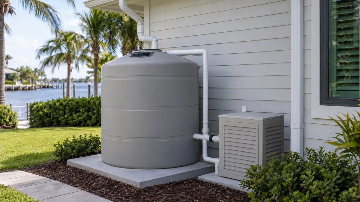
Aboveground storage usually offers simpler exterior inspection and removal, but occupies usable yard space and may affect views. Screened storage is generally an aboveground tank concealed by planting or an enclosure; it retains the same support requirements while adding clearance and access constraints. Buried storage reduces visible bulk but leaves surface access openings and introduces excavation, groundwater, soil-loading, and retrieval demands. Compare the entire disturbed area, including support construction and equipment access, rather than assuming burial causes less landscape disruption.
Foundation proximity, slopes, and retaining structures can eliminate an otherwise attractive location. Tank loading may affect nearby foundations or add surcharge behind a retaining wall; excavation may remove soil that supports either structure. There is no universal safe setback based solely on tank dimensions. A civil or structural engineer should evaluate these relationships, with geotechnical input where bearing conditions, groundwater, or slope stability are uncertain. Existing drainage also constrains placement: a base, enclosure, or raised planting bed must not block a runoff path or redirect surface water toward buildings or neighboring property. Detailed overflow routing belongs in Chapter 8.
Support design must account for the tank, maximum stored water, and equipment. Water weighs approximately 8.34 pounds per US gallon, making a full tank a substantial load even when its footprint is compact. The responsible design professional must reconcile the manufacturer's support requirements with soil bearing conditions and settlement risk. Uneven settlement can distort a tank and strain connections without an obvious support failure. An existing patio or slab is not adequate merely because it looks sound. Roof, deck, or platform placement requires structural engineering of the supporting structure and the complete load path to the ground, including applicable lateral and anchorage demands.
Before considering buried storage feasible, establish seasonal high groundwater, potential floodwater levels, excavation stability, and soil conditions at the proposed location. A dry site visit does not resolve these questions. A nearly empty tank can experience uplift as groundwater rises, so full-tank weight cannot serve as the sole flotation safeguard. Engineering review must address buoyancy resistance, any anchorage, allowable burial depth, and soil and surface loads. Identify whether vehicles, delivery equipment, or future landscape machinery could pass above the tank. Coastal location makes groundwater and storm questions relevant but does not establish conditions on a particular property.
Reserve service space using the selected equipment's instructions and the service contractor's actual maintenance and removal methods. There is no single clearance suitable for every assembly. Technicians need room to operate and replace valves, remove filters or pumps, reach connections, and use tools without dismantling unrelated equipment. Lids need their full opening clearance; vertically removed components need an unobstructed lifting path. Buried tanks still need accessible surface openings. Do not place fixed decking, paving, or planting over access points. Tank entry and technical service remain professional work, not a means of compensating for poor layout.
Screening must preserve those clearances at mature plant size and allow required equipment ventilation. Show removable enclosure sections, gate widths, turning space, steps, eaves, and overhead obstructions on the layout. Distinguish routine technician access from the larger route needed to deliver or replace the tank. A tank installed before a courtyard wall is completed may become impossible to replace without demolition. Where lifting equipment would be needed, establish that a suitable approach and operating position are feasible.
Finally, assess the location from bedrooms, outdoor seating areas, and neighboring properties. Pumps and connected equipment can transmit sound and vibration even though storage itself is quiet; coordinate the location with Chapter 11 rather than relying on screening as soundproofing. Compare the roots, irrigation, paving, and finishes disturbed by each candidate location, including eventual replacement. A visually discreet location may be a poor choice if every major service visit damages established landscaping.
- Can delivery and replacement occur within authorized access routes, with sufficient width, turning room, and overhead clearance?
- Will service openings, valves, and equipment remain reachable after screening and planting mature?
- Are support, settlement, and, where relevant, groundwater and buoyancy questions resolved before the location is accepted?
- Could a less concealed location materially reduce excavation, noise conflicts, demolition, or landscape restoration?
7. Size Storage and Specify the Tank Assembly
Size storage by combining the supply profiles from Chapter 3 with the demand schedule and service priorities from Chapter 4. Roof area alone cannot show whether a tank will bridge dry intervals or sit mostly empty. Compare candidate capacities using the same rainfall sequence, collection losses, demand assumptions, and allocation priorities so the differences reflect storage size rather than changing assumptions.
A time-step model tracks inflow, stored water, demand served, unmet demand, and overflow through successive days or shorter intervals. It must limit withdrawals to available usable water and carry the remaining storage into the next step. Calculation order matters: crediting an entire day's rain before that day's withdrawals can overstate service if demand precedes the storm. Conversely, combining all inflow and demand into a single net daily value can conceal overflow. Smaller tanks and concentrated demand may require shorter intervals.
Run the established typical and dry-period profiles with the planned variation in demand. Initial storage should be stated, with a preceding simulation period or sensitivity check to show whether the assumed starting level materially affects results. Compare demand supplied, shortage frequency, longest shortage, and overflow volume. Where loads have different priorities, report their service separately; a strong overall percentage can conceal poor availability for a particular load.
Advertised capacity is not the same as deliverable storage. The overflow elevation establishes the normal upper water level, often below the tank's total internal volume. The lower operating limit depends on the withdrawal arrangement and low-water cutoff. Sediment space reserves room for settled material; it is not necessarily an additional volume to subtract if it already lies below that limit. Calculate usable capacity between the operating levels using the actual tank geometry, not a simple percentage of advertised volume. Identify these levels on the tank specification; control implementation belongs in Chapter 11.
Compare the marginal benefit of each increase in usable capacity: additional demand served, reduction in shortage duration, and reduction in overflow. A larger tank helps only when surplus inflow arrives before a period that can use it. Storage that seldom fills, or remains full because demand is low, offers little additional supply benefit. A smaller tank may deliver several times its capacity over a season through repeated filling and withdrawal while still providing little dry-period reserve. Use these performance differences in the complete cost comparison in Chapter 12 rather than choosing by cost per advertised gallon alone.
Compare specific products, not material labels. Polyethylene, fiberglass, metal, and concrete tanks differ in joints, liners or coatings, corrosion exposure, handling requirements, and repair options. Require documented suitability for the intended storage application and for aboveground or buried installation as proposed. Include seals, liners, coatings, and fittings in the compatibility review. Opacity should extend to covers and other light-admitting features; limiting light discourages algae but does not replace the treatment decisions in Chapter 10. For equipment exposed to sun, heat, humidity, or salt air, compare documented ultraviolet, temperature, corrosion, and fastener limitations against the actual exposure.
One large tank generally has fewer interconnections and potential leak points, but removing it from service removes all stored supply. Smaller interconnected tanks may simplify delivery and allow partial service during cleaning, provided the assembly supports isolation. Their summed advertised volumes do not necessarily act as one usable reservoir: connection elevations, pipe resistance, and withdrawal rates determine how quickly levels balance. Water can remain stranded in one tank while the tank supplying the pump reaches cutoff. Compare usable capacity and available service with all tanks connected and with one isolated. Each permitted configuration needs appropriate venting and overflow provisions; overflow design is addressed in Chapter 8.
- Specify secure lids and closures that resist unauthorized access and exclude animals and debris. Covers must suit the expected exposure and loading; do not assume an inspection lid is a walking surface.
- Detail mosquito exclusion at inlets, vents, overflows, and other entry paths. Screens and seals must be accessible for professional service, with screen restriction accounted for in airflow and water-flow requirements.
- Specify vents that accommodate both filling and withdrawal without damaging pressure or vacuum. A closed lid is not a substitute for venting, and interconnected tanks should not depend on a connection that may be isolated for their only air path.
- Include tank-specific provisions for sediment removal, internal inspection, drainage, and cleaning, preferably without entry. Homeowners should not enter tanks; internal cleaning and technical service require appropriately qualified licensed professionals. Use the working-space and replacement-access requirements established in Chapter 6 rather than duplicating them.
8. Design Overflow and Full-Tank Behavior
Design overflow for a storm that begins with storage already full. At that point, collection becomes a drainage problem: incoming roof runoff needs a continuous, acceptable route through or around the storage system to a receiving area. The route must work beyond the visible outlet, including when wet ground or elevated downstream water levels limit discharge.
A qualified drainage designer should establish peak inflow from the connected roof catchment identified in Chapter 3, using documented rainfall intensity, storm duration, and a design criterion appropriate to the project and applicable requirements. Annual rainfall and average collection yield cannot size an overflow. Do not credit unused tank volume unless a separately justified detention design establishes that the necessary volume will be available. Ordinary household water use or irrigation demand does not provide that assurance.
Hydraulic capacity depends on the entire route, not just pipe diameter. Calculations should account for the water level needed to drive flow through the overflow entrance, pipe length and slope, bends, protective fittings, and downstream water levels. Screens introduce resistance and can accumulate debris; their effective open area matters more than their outside dimensions. An overflow matching the inlet diameter may still carry less water under its actual operating conditions. The resulting maximum tank water level must remain within the manufacturer's limits rather than allowing restricted discharge to pressurize ordinary storage.
Select the discharge destination before committing to the overflow alignment. Potential destinations include an approved on-site surface drainage feature, an engineered infiltration area, or an authorized drainage connection. Suitability depends on both permission and receiving capacity. A nearby public inlet, existing pipe, easement, or low area is not evidence that the project may discharge there. Routing must not assume permission to send water onto neighboring land or public walking areas.
Compare receiving options under wet conditions. An infiltration feature needs evaluation of soil acceptance, groundwater constraints, available storage, and where excess water travels once that storage fills. A piped connection needs evaluation of downstream surcharge: rising water can reduce discharge or cause reverse flow, depending on the arrangement. Include runoff already reaching the receiving feature, not only the new tank overflow. The shortest connection is not necessarily the most dependable, and infiltration is not a complete solution without an acceptable exceedance path.
Trace surface flow from the outlet to its final receiving area using actual grades. Keep concentrated discharge away from foundations and tank supports, and avoid creating flow across walking surfaces. Evaluate erosion along the route as well as at the outlet, including whether water could strip mulch, expose roots, or carry sediment into downstream drainage. Outlet aprons, energy dissipation, or flow-spreading features must suit the expected discharge and soil conditions. Planting should not conceal the outlet so thoroughly that blockage or scour cannot be observed externally; general access requirements belong in Chapter 6.
Evaluate an obstructed outlet separately from a receiving system that cannot accept water. For each condition, determine how high water rises and where it escapes: through a planned relief route, back toward collection piping, or at an unintended tank opening. Where necessary, provide an independently effective emergency route before water reaches vulnerable components. Two outlets connected to the same blocked pipe do not provide independent protection. An unsecured lid, incidental leakage, or uncontrolled gutter spill is not an emergency drainage design. Also identify the consequences of rainfall exceeding the selected design criterion.
Normal roof drainage must remain dependable when storage is full, isolated for service, or unavailable. A designed collection bypass or equivalent arrangement should preserve that function without requiring homeowner intervention during a storm. Evaluate collection restrictions as well as tank overflow so a blockage upstream cannot defeat roof drainage. Gravity routing avoids dependence on electrical power; any pump-dependent drainage arrangement needs explicit provision for power loss and equipment failure. The rainwater-use pump described in Chapter 11 should not be treated as storm protection.
- Show the complete normal and emergency discharge paths on a coordinated plan and profile, including property boundaries, receiving features, critical elevations, pipe sizes and slopes, and outlet protection.
- Support the plan with peak-inflow and hydraulic calculations identifying the rainfall criterion, allowable tank water level, downstream water-level assumptions, and obstruction and exceedance conditions evaluated.
- Identify who designs and installs any required grading, receiving-feature enlargement, drainage connection, or erosion protection. Resolve dependencies before tank installation rather than leaving drainage improvements as optional later landscaping.
- From accessible ground-level locations, homeowners can document ponding, erosion, sediment deposits, or runoff crossing paths and report changes. These observations inform the design review; alterations and repairs remain professional work.
9. Keep Nonpotable and Drinking-Water Plumbing Separate
The plumbing design should make two distinct networks unmistakable: drinking-water service and dedicated nonpotable rainwater distribution. Drawings should trace every approved rainwater-fed fixture or outlet, distinguish both networks, and detail any location where potable water enters rainwater equipment. No shared distribution branch should depend on someone remembering which supply is selected. Treatment selected for a nonpotable application does not change this separation requirement; treatment decisions belong in Chapter 10.
A cross-connection is an actual or potential connection through which nonpotable water could enter drinking-water plumbing. Reduced potable pressure can cause backsiphonage; a rainwater pump can create backpressure. Normal flow direction therefore provides no reliable boundary. A closed valve is not physical separation: it can leak internally or be opened. A temporary hose linking the supplies creates a hazard while attached, and an improvised two-valve changeover leaves the same vulnerability. Neither a generic check valve nor an automatic controller establishes acceptable separation by itself.
If automatic potable makeup is included, the licensed design team must specify an approved separation arrangement and have the installed interface verified. An air-gapped makeup arrangement provides physical separation: potable water discharges through unobstructed air into a receiving vessel, with the outlet above the applicable flood-level rim. The design must establish the required clearance, receiving geometry, and overflow behavior. Measuring clearance above the normal operating water level is insufficient because that level can rise during a fault. The outlet must remain protected against submergence, and no hose or extension may bridge the gap.
A break tank or packaged makeup unit should be judged by its actual separation detail, not its product name. Its documentation must show where potable delivery terminates and how the approved boundary is maintained. If a backflow-prevention assembly is proposed instead of an air gap at an interface, its acceptability for that specific hazard and application must be established with the relevant authority and water supplier. Such assemblies are not universally permitted substitutes for physical separation. The selected arrangement must also account for any required testing and service access.
The separation decision depends on the service priorities established in Chapter 4. Omitting potable makeup removes that particular interface but means rainwater service can stop when storage is depleted. Automatic makeup supports continuity while adding a protected connection and verification obligations. Resolve that tradeoff before selecting equipment; a future hose connection is not an acceptable backup plan.
Dedicated nonpotable piping needs durable identification along its route and at accessible branches, valves, equipment, and endpoints. The designer should specify the wording, colors, symbols, and marking locations required by the applicable authorities. Color alone is insufficient: markings should plainly identify nonpotable water and state that it is not for drinking. Equipment identification should distinguish potable makeup, rainwater inlet, and nonpotable outlet where present. Labels must remain visible after insulation, screening, and finishes are installed.
Accessible hose outlets need more than a warning sign. An ordinary-looking faucet can invite bottle filling, play-water use, or an unintended connection by a contractor. Eliminate unnecessary outlets and avoid locations where drinking water would reasonably be expected. For outlets that remain, specify appropriate controlled access, lockable enclosures, or approved restricted-use fittings. Closely grouped potable and nonpotable faucets deserve particular scrutiny because labels can be overlooked. Any hose provided for nonpotable service should be clearly identified, dedicated to the approved task, and never used to link the supplies.
Keep the separation-specific records within the home's coordinated handover file: the approved interface detail, as-built routes and connection points, an outlet and valve identification key, and inspection results. Include installed device identification, any required backflow test records, and future verification requirements. These records should let a later plumber trace the boundary without guessing from pipe color or equipment location. Overall acceptance remains part of Chapter 14.
- Drawing check: Every nonpotable endpoint is traceable to its supply, and every potable makeup interface has a specific approved detail rather than a note to connect as needed.
- Access check: Outlet placement and access restrictions address foreseeable misuse by guests and children; signage is not the only protection.
- Observation limit: Homeowners may document visible missing labels, unexpected connecting hoses, or altered makeup outlets. Do not manipulate valves, disconnect suspect piping, or test separation; report suspected cross-connections promptly to the licensed plumber.
- Modification rule: Added outlets, shared branches, hose links, and supply-changeover arrangements require licensed design review and any required approval before work proceeds.
10. Match Treatment to the Approved End Use
Select treatment from the water-quality criteria for each approved application, not from water appearance or a filter catalog. Clear rainwater can contain microorganisms and dissolved contaminants. The design should identify the microbial, physical, and chemical criteria that matter for the intended exposure, their basis in applicable requirements, and the equipment limits needed to meet them. Treatment for a nonpotable application does not establish suitability for drinking, food preparation, or bathing.
Outdoor applications have different treatment needs. Irrigation delivered near soil offers different exposure pathways from spray that can reach people, while narrow emitter passages may require filtration primarily to prevent plugging. Approved indoor nonpotable use can add microbial-control requirements because occupants may encounter splashes or aerosols. Odor, staining, fixture compatibility, and water quality within downstream piping also become important. An outdoor treatment package should not be extended to indoor fixtures without reassessing these demands.
Use the roof and collection assessment in Chapter 5 to identify source-water questions that could change treatment selection. Targeted laboratory testing is useful where source materials suggest a chemical concern, stored-water conditions are uncertain, or the approved use requires verification. Coastal salt deposition may warrant investigation where salinity could affect plants or equipment, but coastal location alone does not establish contamination. Neither sediment filtration nor disinfection reliably removes dissolved salts.
The qualified treatment designer, working with an appropriately accredited laboratory and relevant authorities where needed, should define analytes, sampling methods, locations, timing, and interpretation. Tank samples characterize treatment inputs; treatment-outlet samples assess immediate performance; distant-outlet samples can reveal changes during distribution. Sampling should address consequential conditions such as inflow after a dry interval or prolonged storage, rather than only freshly collected water. A favorable result establishes conditions at that sampling event, not performance across every operating condition.
Sediment removal, finer filtration, and disinfection serve distinct functions. Settling and coarse screening reduce larger particles but are not reliable microbial barriers. Finer filtration can protect emitters and downstream disinfection equipment; a micron rating alone does not establish pathogen removal. Compare documented retention performance, including whether ratings are nominal or absolute, at the proposed flow and loading. Ordinary sediment cartridges do not reliably remove dissolved chemicals. Activated carbon can address selected organic compounds or odor concerns, but its suitability depends on the contaminant, contact conditions, and replacement requirements; it is not a general microbial safeguard.
Disinfection controls susceptible microorganisms without removing sediment or dissolved pollutants. Ultraviolet treatment requires adequate UV transmission, flow within its validated range, and effective lamp and sleeve performance. Suspended particles can shield microorganisms, while some dissolved substances absorb UV even when water looks clear. UV leaves no disinfectant residual to control subsequent growth in piping. Chemical disinfection instead depends on disinfectant demand, contact time, water chemistry, and any required residual; potential by-products may also need evaluation. Dosing and corrective chemical treatment are professional responsibilities, not homeowner adjustments.
Design for variable incoming water rather than a single clean sample. Organic material can increase disinfectant demand and support microbial growth. Warm storage and long residence times during low occupancy can change the treatment challenge. Specify acceptable inlet conditions, including turbidity and any process-specific limits, and determine whether pretreatment can keep water within them. Additional stages should address an identified need: each also adds pressure loss, servicing requirements, and potential failure points.
Treatment capacity must accommodate the maximum permitted flow through the treatment train, not average daily demand. The designer should establish filter service thresholds and select performance indicators appropriate to the process; a power light does not prove effective disinfection. Where indoor distribution permits extended stagnation, the design must address water quality after treatment as well as at the treatment outlet. Coordinate these requirements with Chapter 11's hydraulic design; Chapter 9's plumbing separation remains an independent safeguard.
Define the treatment failure response before selecting equipment. The checklist below establishes the design requirements; Chapter 14 should verify them at acceptance, while Chapters 15 and 16 cover operating and absence procedures. Homeowner involvement is limited to external observation, reporting, and documented normal user controls.
- Set use-suspension thresholds for disinfection faults, flow outside validated limits, inlet water beyond the treatment envelope, unacceptable test results, and suspected contamination.
- Specify when automatic delivery inhibition is necessary rather than an alarm alone, including the safe state following loss of power or a failed monitoring sensor.
- Identify whether a fault affects every connected use or whether an independently protected, approved application can continue. Do not assume untreated water is acceptable elsewhere.
- Assign professional investigation and corrective action, and define the verification required before release back to service. Alarm clearance or improved appearance alone is insufficient.
11. Select Pumps, Controls, and Distribution Performance
Select the pump for the simultaneous loads and service priorities established in Chapter 4. The design duty combines required flow with the pressure needed at the controlling outlet. Scheduling irrigation zones separately or interlocking competing loads may reduce peak demand, but that choice also limits when water is available. Resolve that tradeoff before selecting equipment rather than relying on occupants to avoid inconvenient combinations.
The professional’s hydraulic calculation should include elevation from the operating tank water level to the delivery point, friction through distribution piping and fittings, and losses through valves, filters, and treatment equipment. It must leave adequate residual pressure at the outlet while the selected loads operate. Check low tank level and filters approaching their specified service limit, not only a full tank and clean filters. The highest or farthest outlet is not automatically the most demanding; required outlet pressure and the resistance along each route also matter.
Match these conditions to the manufacturer’s pump curve, not horsepower or advertised maximum flow. Maximum flow and maximum pressure are not generally available together. The selected operating range should remain within the pump’s permitted limits and avoid inefficient operation. Check maximum possible pressure, including shutoff head where applicable, against component ratings and the need for pressure protection. Distribution piping must accommodate the duty without excessive friction or velocity; a larger pump cannot reliably compensate for undersized piping.
Submersible pumps often produce less airborne noise because the water dampens sound, although vibration can still travel through piping and tank supports. Cooling depends on the specified submergence or flow past the motor, and servicing requires a planned professional retrieval method. External pumps make the motor and seals easier to reach but introduce more airborne noise and require appropriate cooling and weather protection. Where an external pump draws water upward, suction lift, inlet-pipe losses, water temperature, and available inlet pressure limit performance. A self-priming designation does not eliminate priming requirements or cavitation risk. Apply Chapter 6’s access provisions, adding pump-specific retrieval and motor-cooling requirements.
Control selection should reflect both long irrigation runs and brief fixture demands. A fixed-speed pump commonly uses a pressure switch and pressure tank, operating between lower start and upper stop pressures. Usable tank drawdown, not shell volume, determines the water available between starts and varies with the selected settings. Variable-speed controls can maintain a narrower pressure range as demand changes, but they add electronics and have minimum-speed, minimum-flow, and cooling limits. They may still need pressure storage, particularly when demand falls below the pump’s stable operating range.
Coordinate pressure settings, pressure-tank drawdown and precharge, allowable starts, minimum run time, and controller response as one design. A pressure tank buffers short demands; it does not replace rainwater storage. The design should explain how a small continuous demand is handled without rapid starts or unstable pressure. For variable-speed equipment, this includes the transition into standby and back into operation. Tank precharge and control adjustments belong to professional setup and service, not homeowner troubleshooting.
Low-water protection should stop the pump before intake submergence or motor-cooling requirements are lost. Separate dry-running protection may be needed because blocked intake flow or lost prime can interrupt delivery even when the tank contains water. Specify detection and response for excessive cycling, excessive run time where appropriate, motor overload, sensor failure, and controller faults. Each condition needs a defined stop, alert, and recovery sequence. Automatic recovery after water returns may be reasonable; repeated retries after an unresolved dry-run or equipment fault can damage equipment. Power-restoration behavior should likewise be deliberate rather than an undocumented default.
Salt air, humidity, heat, and wind-driven rain make enclosure selection more demanding than choosing an assembly merely labeled for outdoor use. The appropriate licensed trades should evaluate corrosion resistance, compatible fasteners, condensation control, cable entries, and heat rejection. Decorative screening must not compromise motor or drive cooling. A licensed electrician should determine supply capacity, starting demands, circuit protection, grounding and bonding, disconnect provisions, and suitable surge protection.
Homeowner displays should distinguish low-water standby from equipment failure. Useful information includes pump state, delivery pressure with an identified normal range, low-water status, and specific fault messages. Remote alerts should identify the affected service and response contact; a readable local display should remain useful without connectivity. Homeowner actions should remain limited to external observation, reporting, and documented normal user controls, including an accessible stop control. Fault instructions must not require panel opening, live testing, bypassing protections, or repeated breaker resetting.
12. Compare Complete Proposals and Ownership Costs
Compare bids against one approved baseline: the same nonpotable uses, usable storage, treatment duties, outlet performance, and service expectations during shortages. Reference the decisions established in Chapters 4 and 7, 11 rather than reopening equipment design in the price comparison. Require departures to appear as separately priced alternatives. A cheaper proposal is not equivalent if it serves fewer loads, omits required treatment, or transfers essential work to another contractor.
Build a comparison sheet with a column for each bidder and a row for each cost category. Distinguish design and trade coordination; equipment; delivery and placement; installation; applicable approval services and fees; commissioning and handover; and optional enhancements. Identify taxes where applicable and whether they are included. Keep appearance upgrades and convenience features separate from the baseline unless they are necessary to satisfy an established project requirement. Record quote expiration dates and any price-escalation provisions so apparently comparable totals do not conceal different purchasing risks.
Mark every line as fixed-price, allowance, excluded, or unresolved. An allowance is a placeholder, not a completed scope assessment: record its quantity and site assumptions, what triggers adjustment, and how unused amounts or overruns are reconciled. For essential excluded work, obtain a separate price and assign responsibility before comparing complete project totals. Avoid double-counting work included by two trades. Keep an owner contingency for unresolved conditions separate from the contractor's price; it does not authorize additional work.
Use the same ownership period for every proposal. Show the complete initial cost, annual operating and service costs, and replacements expected within that period. Recurring entries should include pump and treatment electricity, filters and other consumables, laboratory testing, scheduled professional service, and any monitoring subscriptions. Include professional absence and return-to-service visits if the operating plan requires them. Distinguish required service from optional service packages, and check whether quoted visits include consumables, testing, travel, and disposal or charge for them separately.
Require a basis for each recurring estimate: equipment demand and operating hours for electricity, specified intervals and loading assumptions for consumables, and service-provider pricing for routine visits. Replacement budgets should include removal, installation, and recommissioning, not just the replacement part. Use the access plan established in Chapter 6 to identify unusual replacement labor or screening-removal costs without redesigning the location here. Treat component life as an estimate, not a promise; warranty length alone is not a replacement schedule. Show a reasonable higher-service-cost case where intervals or exposure-related costs remain uncertain.
Estimate purchased-water savings using the applicable account, meter, rate schedule, and billing periods. Start with estimated rainwater actually delivered to the approved loads, not roof runoff or tank capacity. Compare the expected utility bill with and without that reduction in each period. Tiered charges may make the value of avoided gallons vary with household consumption, while fixed charges may remain unchanged. Include wastewater savings only if the applicable billing method would actually reduce those charges. Avoid counting reduced irrigation demand from unrelated landscape improvements as a rainwater-system benefit.
Keep avoided utility charges separate from net savings. Subtract recurring ownership expenses for an annual cash comparison, then include initial costs and expected replacements in the longer-term total. State assumptions about future utility rates and service costs consistently across bids. Test whether the decision changes with lower rainwater deliveries, higher service costs, or earlier replacement. If cumulative savings do not recover the investment within the evaluation period, state that plainly; conservation and convenience can remain valid priorities without being presented as financial returns.
Turn the selected proposal into enforceable scope rather than relying on product brochures. Specify equipment or measurable equivalence criteria and require owner approval before substitution. Change orders should state scope, price, and schedule effects before changed work proceeds. Distinguish equipment warranties from workmanship coverage, including claim responsibility, labor, travel, exclusions, and start dates. Tie payment milestones to defined deliverables and acceptance under Chapter 14, including the agreed performance records. Name one party to coordinate cross-trade defects, with a correction process and deadlines; clarify responsibility and payment treatment for unresolved or deferred items.
- Roof and collection exclusions: Price required roof modifications, gutter changes, and downspout rerouting; identify responsibility for roof-warranty implications.
- Groundwork exclusions: Check excavation, access constraints, spoil removal, unsuitable-ground allowances, and the conditions that trigger additional charges.
- Trade exclusions: Resolve electrical supply, plumbing connections, dedicated distribution, and required separation work labeled “by others.”
- Drainage and restoration exclusions: Include necessary drainage alterations and the stated extent of screening, paving, landscape, and finish restoration.
- Acceptance costs: Confirm that commissioning against approved criteria, required performance documentation, and correction of installation deficiencies are included, not merely equipment startup.
13. Plan Installation Around the Occupied Home
Build the installation schedule around trade handoffs and household access, not just a promised finish date. The lead contractor should identify dependencies, inspection hold points, and tasks that can proceed in parallel without competing for the same space. Confirm tank delivery and lifting arrangements before opening areas that cannot remain safely exposed through a delay. Include allowances for weather, inspection availability, and unexpected buried obstructions rather than treating every workday as interchangeable.
Before mobilization, the professionals directing excavation should coordinate utility locating and establish what the locating service does and does not cover. Private irrigation, landscape lighting, pool services, and other buried lines may need separate investigation. Existing homeowner drawings are useful leads, not clearance to dig. Unresolved locations require professional investigation before excavation proceeds. Proposed cuts through walls, slabs, or foundations also need review by the responsible licensed trade and, where structural implications exist, a structural engineer before cutting starts.
A workable sequence begins with condition photographs, finish protection, barriers, and layout. Prepare tank support or excavation while preserving the delivery route, then coordinate underground collection, overflow, distribution, and electrical work. Tank placement must occur before screens, fences, or other completed work block lifting access. Roof work can proceed in parallel only where crews and equipment do not conflict. Schedule the collection changeover after the receiving assembly is ready, using the drainage provisions established in Chapter 8 rather than improvising a temporary discharge.
Coordinate trench corridors before digging: different services may have different slope, bedding, separation, and inspection requirements. Licensed trades should complete rough-ins and required preclosure checks before backfill or wall repairs. Electrical rough-in may precede pump placement; final wiring and energization belong to the licensed electrician. Final connections follow equipment placement and the applicable inspections. Keep screening unfinished until the access provisions established in Chapter 6 have been checked. Startup and acceptance belong to Chapter 14, not to the milestone labeled 'installation complete.'
Use an interruption schedule that distinguishes loss of drinking-water service, irrigation, electricity, and access to particular rooms or entrances. Do not assume the whole home must shut down for each trade. For every actual interruption, identify the affected area, expected duration, notice period, responsible contact, and fallback if restoration slips beyond the workday. Schedule dust-producing cutting and interior access around occupancy. If essential bathrooms or safe entrances cannot remain available, reschedule that phase or arrange temporary vacancy; an estimated afternoon finish is not a sufficient contingency.
For guest-used spaces, one owner or property-manager contact should control access arrangements and communicate changed restrictions. Delivery and lifting plans should identify truck staging, overhead obstructions, ground-bearing conditions, and exclusion zones without assuming use of neighboring property. Professionals must assess equipment travel over paving and near buried structures. Keep occupants out of lifting areas and separate them from trenches, tools, and unsecured components with barriers appropriate to the hazard; caution tape alone may not prevent entry by children or guests.
Require an end-of-day and storm securing plan for roof openings, excavations, tanks, and loose materials. Phased excavation can reduce the amount left exposed, but may require repeated mobilization and longer disruption along the access route. Compare those consequences before work starts. Weather pressure must not become a reason to cover work before inspection.
Set explicit closure hold points for trenches, walls, and equipment surrounds. Before concealment, the responsible trades should arrange required inspections and record buried routes and junctions, bedding, tank support or anchoring, penetrations, and concealed service identification. Photographs need both context and detail, with installer-recorded dimensions referenced to fixed features. They supplement, not replace, inspections. The schedule should identify who releases each hold point and what happens if a check fails.
- Establish the condition baseline jointly: photograph paving, finishes, planting, and irrigation along work and delivery routes. Mark no-storage areas and specify protection for fragile surfaces before deliveries arrive.
- Separate daily cleanup from final cleanup. Define dust containment, debris and loose-fastener removal, secure material storage, and protected walking routes that remain usable between contractor visits.
- Define restoration boundaries: trench settlement correction, planting replacement, irrigation repairs, paving reinstatement, and finish patching. Specify whether the intended finish result requires a localized patch or treatment of a larger visible area.
- Assign responsibility for trade-caused damage, including damage discovered after backfill, and name the contractor coordinating restoration. Establish how concealed surprises trigger a pause and authorization before additional work proceeds.
- Complete final landscape and surface restoration after heavy access ends. Where permanent repairs must wait, identify the safe temporary surface, who maintains it, and the milestone for its replacement.
14. Verify the Finished System Before Acceptance
Commissioning should establish whether the finished installation meets the approved design and accepted proposal. Use a single checklist with a pass, fail, or deferred result for each applicable item. Before testing, the coordinating professional should identify the acceptance criterion, test method, responsible trade, and required evidence. Missing criteria require resolution with the designer; they should not be improvised during the walkthrough.
A pass applies only to the conditions actually verified. Record test loads, tank level, relevant settings, instruments used, and any limitations. A deferred test is not a pass: identify why it remains incomplete, who will complete it, and whether it prevents acceptance or release of the affected use. Homeowners may witness accessible equipment, record observations, and use documented normal user controls; technical testing and corrective work remain with the appropriate licensed professionals.
- Installed scope , PASS when equipment identification, connected catchments, storage assembly, distribution destinations, and routing match the approved documents and accepted changes. Compare concealed routing with construction photographs and inspection records. Confirm that service access specified in Chapter 6 remains available. An as-built drawing records a deviation; it does not by itself approve one.
- Collection delivery , PASS when the tested catchments deliver water through the specified interception, diversion, and filtration path without unintended bypass, backup, or leakage. Identify each catchment tested and whether evidence came from rainfall or a controlled test. Controlled water introduction must not create a drinking-water cross-connection. Limited test flow verifies routing, not design-storm capacity; retain the Chapter 8 calculations as separate evidence.
- Storage and level behavior , PASS when professionally verified water levels agree with the displayed indication within the specified tolerance, and operating thresholds correspond to the approved usable range. Check tank connections and accessible surrounding surfaces for unintended leakage during the specified test period. Investigate unexplained wetness rather than accepting an assumed cause.
- Overflow , PASS when an appropriately controlled test confirms entry into the overflow, the intended discharge route, and acceptable visible discharge behavior. The test must not flood the site. Record any unverified full-tank or downstream condition as deferred, with the designer's determination of what further evidence is needed. Do not infer full drainage capacity from a small overflow test.
- Delivery performance , For pumped systems, PASS when measured flow and operating pressure meet the Chapter 11 criteria at the specified measurement points and approved loads, including simultaneous demand where applicable. Record active outlets or zones and tank level. A static pressure reading or successful operation of one convenient outlet is not a substitute for the required loaded test.
- Controls and protection , PASS when professional testing demonstrates normal starts and stops, acceptable cycling, specified alarms, low-water shutdown, and the intended restart sequence. Use manufacturer-approved methods without deliberately running the pump dry or bypassing protection. After a planned normal interruption, verify recovery to the specified operating state, including any required manual acknowledgment, without unintended delivery.
- Treatment and release for use , PASS when the Chapter 10 startup requirements are complete and treatment indicators meet specified limits under the tested flow conditions. Where water-quality verification is required, retain sampling details, laboratory results, and the responsible professional's interpretation against the approved criteria. Pending or unacceptable results leave the affected use unreleased under Chapter 10's response plan. Record release status separately for each approved use.
- Handover baseline , PASS when the commissioning report includes applicable loaded flow and pressure, tank-level indication, filter pressure differential, treatment status, and control settings with their test conditions. Link it to the final drawings, equipment and warranty records, and separation and inspection evidence already required elsewhere in this guide. Missing records needed to operate or service the installation remain punch-list items.
- Owner demonstration , PASS when the homeowner can identify normal indications, recognize alerts, locate instructions, and explain the documented user-level response and service contact. Demonstrate only external observation and normal user controls. Do not include opening electrical enclosures, adjusting protective settings, or performing maintenance.
- Punch-list closure , Give each failed or deferred item a dated entry identifying its location, unmet criterion, evidence, responsible contractor, resolution date, and required retest. Distinguish items blocking use from finish-only defects. Leakage at commissioning, incorrect routing, missing labels, and failed controls are acceptance defects; later scheduled consumable replacement is maintenance. Unusually early deterioration warrants review rather than automatic assignment to the homeowner. Close items with corrective-work evidence and affected retest results, and handle conditional acceptance and payment milestones under the contract without representing deferred performance as verified.
15. Maintain Performance Through Observation and Professional Service
Use the commissioning baseline from Chapter 14 to recognize changes in operation. Homeowner activities are limited to external observation, reporting, and documented normal user controls. Maintenance and technical service belong to appropriately qualified, licensed professionals. Continued water delivery is not a reason to defer scheduled service.
Observe from stable ground without climbing, opening tank lids or equipment covers, or reaching into screens. Record visible debris accumulation, detached collection components, damaged protective openings, tank distortion, and changes in supports or surrounding ground. Read accessible external level and status displays. Note new rattling, grinding, or repeated pump starts, including whether an outlet was operating. Photograph exterior moisture and record whether it follows rainfall or persists in dry weather. Visible corrosion on housings or fasteners merits reporting, especially with salt exposure, but its appearance alone cannot establish the condition beneath it.
Build a task-by-task maintenance schedule from manufacturer instructions, treatment requirements, and operating experience. Each entry should identify the responsible service provider, the applicable time, operating-hour, volume, or condition trigger, and the next due point. Where several limits apply, follow the governing instructions rather than selecting the most convenient interval. Actual debris loading may require earlier filter or screen service; light use does not by itself justify extending treatment-component replacement or testing intervals. Have the contractor adjust inspection frequency when service findings show that the original schedule is too sparse.
Supplement calendar reminders with event-driven observations. Once conditions are safe after a storm, check accessible exterior areas for displaced components, accumulated debris, and new wet spots. Report roof or landscape work that may have changed debris loading or affected equipment. Refer changes in runoff suitability to the review in Chapter 5 rather than treating them as routine filter problems. A sudden increase in service demand after a particular event is useful information for the contractor.
Assign tank entry, internal cleaning, sediment removal, filter service, pressurized piping work, electrical service, installation, and repairs to professionals qualified and licensed for the work involved. Tank entry requires specialist confined-space assessment and procedures; an empty tank is not automatically safe. Do not drain the tank, loosen fittings, open electrical enclosures, adjust pressure controls, reset breakers repeatedly, or bypass protective devices to investigate a symptom.
Track trends under comparable operating conditions rather than relying on isolated impressions. Compare pump starts during the same irrigation zone or other established load, available flow at the same outlet, and filter service intervals against rainfall and debris conditions. Distinguish reduced delivery at one outlet from reduced delivery throughout the system. Compare displayed tank-level changes with known use, rain, and any automatic makeup operation. Shorter filter intervals, more frequent cycling, or unexplained stored-water depletion can identify deterioration worth investigating, but none proves a particular fault. Ask whether service restored the baseline before treating repeated component replacement as a satisfactory solution.
For treatment alarms, failed verification, unexpected water odor or appearance, or suspected contamination, stop the affected use and follow the response plan established under Chapter 10. Persistent leakage, rapid abnormal cycling, loss of delivery despite an apparently adequate stored level, and damaged tank security also warrant stopping affected operation and requesting service. Smoke, burning odors, exposed wiring, or water around electrical equipment require keeping away and seeking urgent assistance. Use a documented owner shutdown control only if safely accessible; do not approach a hazard to operate it. Do not add chemicals or change settings as a remedy.
Keep a focused service history: the symptom, operating context, contractor findings, work performed, consumables used, relevant test results, and performance afterward. Record component installation dates and distinguish preventive replacements from fault-driven ones. These records reveal whether costs arise from normal consumption, worsening source conditions, or recurring unresolved failures. Feed that evidence into the ownership budget framework in Chapter 12. For repair-versus-renewal decisions, compare the expected restoration of dependable service, parts availability, downtime, and continued treatment support, not component age alone.
- At each observation: record the date, recent weather, active load, displayed level or alert, and what differs from normal.
- At each service visit: review overdue tasks, shortening consumable intervals, repeat faults, and whether the findings justify an earlier next visit.
- At budget review: identify components approaching manufacturer service limits or losing parts support, then obtain current professional estimates rather than assuming last year's repair expense will continue unchanged.
16. Prepare for Absences, Rental Handoffs, and Future Changes
Have the designer and service contractor establish an absence plan before a long vacancy or low-use season. Choose between continued operation with scheduled oversight and taking designated uses out of service. Compare the need for unattended irrigation, treatment-service obligations, response availability, and the time needed to restore service before occupants arrive. The plan should identify who receives alerts, who can authorize service, and who takes over if the primary contact cannot respond. Remote notifications are useful only when someone is responsible for acting on them.
Low occupancy is not necessarily equivalent to shutdown: irrigation may continue while indoor demand disappears, changing water turnover and equipment operation. The contractor should specify the appropriate storage and treatment condition for each absence mode, including whether water remains in storage and whether any professional draining or isolation is needed. Retain the full-tank and drainage provisions established in Chapter 8; stopping distribution does not stop incoming roof runoff. Homeowners and managers should use only documented normal user controls, not devise their own shutdown sequence.
Schedule the return review far enough ahead of occupancy to allow service or testing specified by the plan. Give the contractor the vacancy dates and records of power interruptions, missed visits, alerts, or storm damage. Use the treatment-release criteria in Chapter 10 and the service-response rules in Chapter 15 rather than creating a separate, less demanding rental standard. If readiness remains unresolved, tell arriving occupants which uses are unavailable and provide only the alternative already accepted in the design. Do not promise restoration by check-in before the contractor has confirmed readiness.
Give guests a short instruction card tied to the outlets they can actually encounter: “Outlets marked nonpotable supply collected rainwater. Do not use it for drinking, food preparation, or bathing. Supply may stop when stored water is low. Do not adjust equipment or connect one water supply to another. Stop using an affected outlet if you notice a problem, and contact [designated contact].” Replace the placeholder, identify the actual outlet locations and permitted uses, and state whether an approved alternative is available. Keep the card consistent with permanent labels; guests do not need the technical manual.
The property manager coordinates people and access; the service contractor resolves technical conditions. Following the operating plan, the manager notifies occupants, communicates use restrictions, records displayed alerts and externally visible conditions, and arranges service. Observation, reporting, and documented normal user controls define that role, not maintenance or troubleshooting. The appropriately licensed service team investigates, performs required work, and documents release under the established criteria. Set spending authority, escalation contacts, and arrangements for unavailable service before a rental begins so guest pressure does not lead to an improvised supply connection.
Review proposed changes before purchasing equipment or authorizing connections. The triggers below identify when the accepted design may no longer fit; they are not instructions to resize or modify the system informally. Include temporary work, such as roof cleaning, in advance coordination because collection may need professional isolation even when the permanent design is unchanged.
At sale, transfer the current system file assembled through Chapters 9, 14, and 15 rather than building a second archive. Add the absence plan, current response contacts, unresolved restrictions, and a clear statement of which uses are presently in service. Ensure the latest as-built records distinguish active, disconnected, and abandoned concealed piping. Arrange a service-provider orientation, and confirm who will receive alerts after ownership changes. Transfer necessary account access securely and remove former-owner access without interrupting monitoring.
If the system is no longer wanted, commission professional decommissioning rather than leaving unused equipment in place indefinitely. The plan should establish an acceptable destination for remaining water, removal or permanent disconnection of distribution and makeup connections, retirement of electrical and treatment equipment, and removal of misleading outlet identification. Decide whether storage will be removed or retained securely; buried tanks need assessment of stability and the proposed abandonment or removal method. Require verification that ordinary roof drainage is restored, using the drainage criteria in Chapter 8. Record any retained tank or abandoned piping and its continuing inspection or security obligations.
- Occupancy: Will more guests, longer vacancies, or a different rental schedule change peak demand, turnover, or the ability to respond to alerts?
- Landscaping: Will new planting or irrigation zones change seasonal demand, simultaneous flow, pressure needs, or service priorities?
- Roof work: Will replacement materials, coatings, cleaning products, or altered downspouts change runoff suitability or the connected collection area?
- Fixtures and uses: Will added outlets, appliances, or indoor applications change approved uses, treatment duties, or plumbing-separation requirements?
About this guide: This resource provides general homeowner education, not a remote diagnosis. Actual conditions, code requirements, equipment, and safe repair options must be evaluated at the property.