Do not remove an electrical panel cover, touch exposed conductors, bypass protection, or repeatedly reset a fault. Keep clear of smoke, sparks, burning odors, hot equipment, standing water near electricity, and downed lines, then call qualified help.
1. Define the Modernization Around How the Home Will Be Used
Start with what the household needs to accomplish, not which equipment to replace. Supporting new appliances, improving visibility, ending everyday dependence on inconvenient extension cords, protecting electronics and accommodating changing needs are outcomes. “Replace the panel” is a proposed solution. A useful project brief gives the licensed electrician a clear purpose without predetermining the technical answer.
Rank outcomes by consequence, frequency and dependency. Which limitation interferes with daily life? Which change supports an occupant’s independence? Which decision anchors an already committed renovation? Separate must-deliver outcomes from improvements worth including if practical and preferences that can wait. When priorities compete, identify what you would defer first. Accessibility may outweigh frequency of use, while a committed cooking change may take precedence over decorative improvements. Avoid broad promises such as “make everything more reliable”: protecting electronics from damage, avoiding lost work and operating during an outage are different goals. Identify the desired result here; Chapters 9 and 11 address protection and continuity.
Describe occupancy through operating assumptions rather than labels. For full-time living, record a normal busy day and recurring overlaps among cooking, work, laundry and leisure. For seasonal use, distinguish occupied periods from vacancy: what remains in use, who returns first and whether a full household arrives together. Shorter occupancy does not necessarily mean less intensive use during visits. Multigenerational living may involve different sleep schedules, abilities and expectations for shared rooms. Occasional rental use makes understandable everyday operation important for unfamiliar occupants; it does not require a separate troubleshooting plan at this stage. Note who must be able to use essential features independently.
Review rooms by activity before requesting outlet or fixture counts. For each space, describe who uses it, what they do, when activities overlap and what currently gets in the way. A kitchen used for simultaneous meal preparation and homework presents a different problem from one used only for cooking. A guest room becoming a regular caregiving space changes priorities even if its dimensions remain unchanged. Include movable activities: if work routinely shifts between a desk and dining table, decide whether that flexibility is intentional or merely a workaround. These distinctions help establish the room’s purpose; detailed receptacle placement and lighting design belong in Chapters 5 and 7.
Classify each proposed change by commitment. Confirmed scope reflects an owner decision to proceed with a use or function, even if the product is not selected. Reasonably likely scope has a credible trigger within several years, such as an expected household change or an established hobby outgrowing its present space. Give it an approximate decision window and identify what remains uncertain. Speculative scope lacks a settled purpose, location or timing and should not authorize immediate equipment purchases. An unresolved choice between a workshop and a caregiver room is a room-use decision first, not a reason to buy equipment for both. Chapters 3 and 10 address capacity assumptions and provisions for deferred additions.
Resolve conflicts that would otherwise produce incompatible requests. If the same room must support quiet work and noisy hobbies, decide whether those activities need different spaces or occur at different times. If essential controls must suit both a technology-comfortable owner and an occupant who prefers simple operation, record whose needs govern. Where a decision cannot yet be made, state the alternatives rather than presenting both as confirmed requirements.
Keep the brief short enough to guide decisions. Completion criteria should describe observable use, not promise technical performance that has not been assessed. For example, the agreed office arrangement should be usable without cords crossing its walking route, and the intended occupant should be able to operate essential lighting comfortably. These criteria establish intent now and become the basis for later design review and completion checks.
- Priorities: List the must-deliver outcomes in order, with the preferences that can be deferred to preserve them.
- Operating assumptions: Record household size, occupancy patterns, consequential activity overlaps and independent-use needs.
- Scope boundaries: Identify included rooms, confirmed changes, likely additions with decision triggers, speculative ideas and explicit exclusions.
- Constraints: Note renovation dependencies, timing limitations and finishes the owner hopes to preserve. Develop the consolidated budget in Chapter 13.
- Open decisions: Assign each unresolved room-use or household requirement to a decision-maker and a decision date.
- Approval baseline: Date the brief and name the owner’s scope approver. Evaluate new requests as additions, substitutions or deferrals rather than silently absorbing them into the original project.
2. Assemble a Safe, Useful Record of the Existing Home
Build an existing-condition record that distinguishes documented history, homeowner observations and professionally verified findings. Give entries a location, source and approximate date. This prevents an invoice for a kitchen remodel from becoming an unsupported assumption that all kitchen wiring was replaced. Missing information should remain marked unknown rather than filled in from a room’s appearance or apparent age.
Collect prior electrical invoices, renovation drawings, available inspection records, utility bills and appliance manuals. Each answers a different question. Invoices describe reported work, not the condition of unrelated circuits. Drawings show intended arrangements unless verified as built. Inspection records document a particular review and outcome, not today’s whole-home condition. Bills describe consumption, not wiring integrity or available capacity; Chapter 3 addresses their use in capacity planning. Manuals identify model-specific requirements but do not prove that the installed connection meets them. Flag conflicts between records so the electrician can investigate specific discrepancies.
Photograph equipment labels visible from a safe, normally accessible position without opening equipment, reaching behind it or moving appliances. Model, serial and rating information helps identify manufacturer documentation, but a label cannot establish internal condition or compatibility of every installed component. Include any circuit-directory copy already available and note known errors without guessing at corrections. Leave unreadable or inaccessible information as a gap; do not open a panel to obtain it.
Make a room-by-room sketch of visible receptacles, switches, fixed lighting and installed equipment. Use recognizable locations such as 'wall beside hall door,' with matching photo identifiers where useful. Record switch functions known from ordinary use and mark uncertain functions unknown. Note areas obscured by cabinetry or furniture as not observed. Include ordinarily accessible exterior and utility areas without removing covers or testing circuits. This is an inventory of locations, not a verified circuit map; planning new connection locations belongs in Chapter 5.
Keep a symptom history with approximate timing, frequency, duration, affected equipment and operating conditions already observed. Useful details include whether flickering affected one lamp or several rooms, whether power loss affected one appliance or multiple devices, and whether the event coincided with appliance startup, simultaneous use, wet weather or return after a vacancy. Record prior breaker trips, unusual sounds, odors and visible discoloration without diagnosing them. Do not reproduce faults or repeatedly reset breakers. Stop using suspect equipment and seek prompt professional guidance; keep clear of smoke or sparking and call emergency services if fire is suspected.
Before recommending reuse, the licensed electrician should reconcile the records with actual circuit and equipment arrangements. Unknown alterations, inaccurate directories and undocumented additions may require targeted circuit tracing, inspection and appropriate testing. Each unresolved condition should be linked to the decision it affects: retaining a circuit, supplying new equipment or relying on an existing junction. An inaccessible junction or concealed transition is a limitation, not evidence of an acceptable connection. Necessary professional access should be identified before design depends on that wiring; Chapter 12 covers access and restoration planning.
The professional baseline should identify what was examined: wiring methods and conductor materials; observable insulation and termination condition; circuit protection; equipment ratings and component compatibility; and grounding and bonding condition. It should distinguish visual observations from test results and identify unexamined portions. Findings such as overheating, corrosion, moisture effects, physical damage or unsuitable alterations need an explanation of their significance. Age can suggest materials and service history, but neither recent installation nor decades of operation establishes acceptable condition. Actual exposure and observed deterioration matter more than assumptions based on a coastal address.
Request a condition report organized into the four categories below. For each finding, identify its location, evidence, recommended action and limits of certainty. A report that distinguishes confirmed defects from unresolved questions supports selective reuse without turning every uncertainty into either a replacement recommendation or an assumption of safety.
- Immediate hazards: Identify conditions needing prompt action independent of the renovation, including any professional restrictions on continued use. Do not leave these in a general list of future upgrades.
- Work required for the proposed renovation: Explain which planned change makes the work necessary and what existing condition prevents the proposed use without modification.
- Optional improvements: State the specific benefit and distinguish it from correction of a hazard or a requirement of the planned work.
- Further investigation: Name the unanswered question, the access or evaluation needed, and the design or reuse decision that must remain open until the finding is resolved.
3. Turn Present and Future Loads Into Capacity Decisions
Capacity planning should identify which part of the electrical system limits the proposed work before anyone selects a service size. A licensed electrician’s formal load calculation evaluates retained loads, renovation changes and defined future additions using an applicable method. It assumes neither that everything runs at full output together nor that household habits reliably prevent overlap. Equipment condition remains a separate gate: sufficient calculated capacity does not establish suitability for continued use.
For retained and proposed equipment, the electrician needs rated voltage, electrical input watts or amperes, relevant motor ratings, operating duration and manufacturer supply requirements. Identify equipment being removed so replacements are not counted twice. Heating and cooling inputs should distinguish compressors, auxiliary electric heat and components that can operate together. Workshop inputs should identify simultaneous tool use, starting characteristics and automatic loads such as compressors. Building information, including floor area and general-use loads, also enters the calculation. Use the records assembled in Chapter 2; final appliance-model coordination belongs in Chapter 6.
Breaker totals and advertising claims cannot replace these inputs. Breaker ratings concern circuit protection, not actual equipment demand; their sum does not establish required service capacity. Cooling output, advertised tool horsepower and cooking performance may not describe electrical input. The calculation applies the relevant treatment of general loads, appliances, motors, continuous loads and permitted diversity, not an owner-selected discount. Motor starting may also require a separate performance evaluation: meeting a demand calculation does not by itself resolve voltage-drop or starting concerns.
Consumption history provides context, not a stand-alone capacity verdict. Monthly kilowatt-hours measure energy over time, not the highest simultaneous demand. Low consumption during seasonal vacancy says little about occupied periods when cooling, cooking and laundry overlap. Utility interval records can reveal patterns, but averaging may obscure short peaks, and historical records omit future equipment. If an applicable assessment method permits measured existing demand, the electrician must establish whether the data resolution, observation period and treatment of added loads meet that method’s requirements.
Represent future loads with bounded scenarios. Start with retained equipment and confirmed additions, then evaluate reasonably likely additions using candidate input ratings or a defined range. Ask which uncertainty changes the decision: a higher-input cooking appliance, auxiliary electric heat or another substantial motor load. The useful result is a threshold for reconsidering service, feeder or management capacity, not an unsupported statement that the home has room for anything. Do not automatically count every speculative purchase at its maximum rating. Chapter 10 addresses whether to install, enable or defer future provisions.
Once these inputs are sufficiently defined, compare retaining the service, upgrading it and using an approved load-management approach. Retention can be appropriate when calculated demand fits and equipment is suitable, even if downstream work is substantial. An upgrade may support greater concurrent use but can require utility coordination and changes beyond the panel. Load management may avoid or defer an upgrade by limiting eligible flexible loads; it exchanges some equipment availability for controlled demand.
For management options, compare exactly which loads can be delayed or reduced, acceptable interruption duration, effects on occupant routines, compatibility and continuing support. The design must address the relevant service and feeder limits and establish safe behavior if controls or communications fail. A preferred schedule is not an enforced limit, and service-level management cannot make an undersized branch circuit adequate. For a workshop, distinguish optional flexible loads from equipment needed together: interrupting dust collection while a saw operates is not an equivalent trade-off to delaying vehicle charging.
- Whole-service capacity: Does the calculated household demand fit the supply and service-component ratings? Identify the limiting component rather than relying on the panel’s advertised rating alone.
- Feeder capacity: Can the supply to downstream distribution equipment carry its assigned loads? A workshop feeder may need changes even when whole-service capacity is sufficient.
- Branch-circuit capacity: Can each circuit support its assigned appliance or group of loads? Service headroom does not establish that an existing appliance circuit is adequate.
- Breaker positions: Can the required protective devices fit in an approved equipment configuration? Empty positions do not prove electrical headroom, and a full panel does not by itself justify a service upgrade. Distribution-layout choices belong in Chapter 4.
- Decision comparison: For each viable option, identify the constraint it resolves, permitted concurrent use, operating restrictions, starting-performance concerns and assumptions that would trigger reevaluation. Compare those outcomes, not service amperage alone.
4. Plan the Distribution Layout, Not Just a Panel Replacement
A distribution layout defines how service equipment, disconnects, feeders and panels relate to one another. Use the existing-condition assessment, Chapter 3’s capacity conclusions and the renovation floor plan to decide which distribution points to retain, replace or relocate. Resolve those relationships before selecting panel models: a new panel in the old location can still leave awkward access, confusing supply paths or conflicts with renovated rooms.
Retain equipment when its assessed condition, ratings, compatible protective devices and circuit accommodation support the approved design. Replace it in place when the location remains suitable but deterioration, inadequate ratings or unavailable suitable components prevent reuse. Relocate equipment when the location, not merely the equipment, is the problem. A wall assigned to cabinetry or a room changing use may make an otherwise serviceable panel unsuitable there. Compare alternatives by the equipment genuinely reusable, feeder changes required, access preserved and maintenance points retained. Each intermediate panel should have a clear continuing purpose; fewer panels are not automatically better, but unnecessary ones add complexity.
A subpanel can serve an addition or distant work area effectively when several circuits benefit from a nearby distribution point. Compare that arrangement with individual branch circuits from an existing panel. The designer should evaluate circuit count, route lengths, voltage drop, upstream accommodation and suitable mounting space. A local panel may simplify branch-circuit routes while introducing a feeder and another equipment location that must remain accessible. It does not add utility service capacity; use Chapter 3’s findings to establish what loads the arrangement can support.
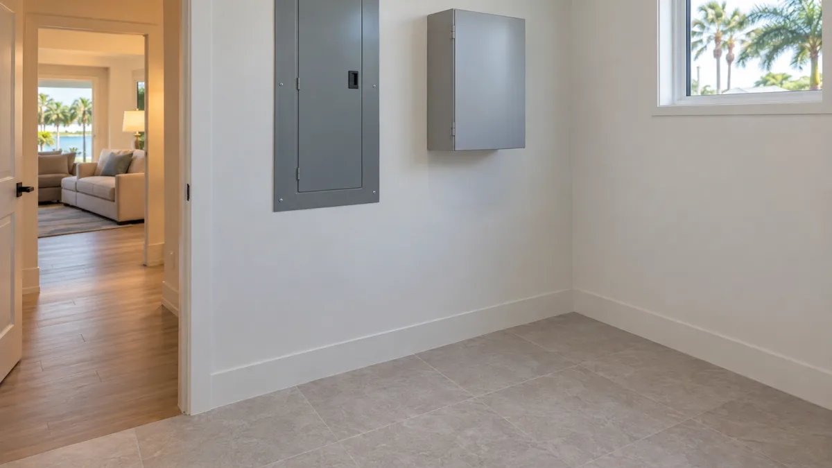
Coordinate electrical locations with cabinet elevations, doors, storage and intended room uses, not just panel symbols on a floor plan. The designer should show applicable working space, headroom, equipment-door operation and dedicated equipment space. A cabinet above equipment, a new partition or a conflicting door swing can undermine an otherwise plausible location. Access should not depend on routinely moving bicycles or supplies. Also ask whether qualified personnel could service or replace the equipment without dismantling fixed furnishings. Resolve these conflicts before cabinet fabrication; detailed routing and finish-restoration choices belong in Chapter 12.
An equipment proposal should identify the manufacturer and product series or model, its service-equipment or downstream role, voltage and current ratings, and enclosure suitability. It should also identify applicable interrupting and short-circuit ratings, with the designer establishing suitability for available fault current. Specify permitted protective-device types for the planned design rather than accepting an unspecified breaker assortment. Physical breaker spaces and permitted circuit configurations are different product characteristics; compact breaker arrangements are not universally allowed. Compare manufacturer documentation, suitable replacement-device availability and technical support. Matching dimensions or ampere ratings do not make two panels interchangeable, so substitutions require review against both the electrical design and the location plan.
Make the supply relationships understandable. Assign each panel a distinct identifier and group served areas or functions coherently where practical. A downstream panel serving a clearly defined addition may be easier to maintain than circuits scattered among unrelated panels. Conversely, a chain of panels with poorly defined purposes can complicate isolation. Identify each panel’s upstream source and disconnect relationship, along with any additional supply sources included in the project. Labels and diagrams assist qualified personnel in planning isolation; a labeled disconnect being open does not establish that equipment is safe to work on.
Before approving the layout, review the following three coordinated design records. They should explain the proposed architecture without becoming installation instructions. Match identifiers across the records and renovation drawings, and mark unresolved selections. These design records become the basis for Chapter 15’s field-verified closeout information.
- Conceptual one-line diagram: Show the service connection, disconnects, panels, feeder relationships and key ratings. It should make clear which equipment supplies which downstream panel and distinguish existing equipment retained from proposed changes.
- Proposed panel schedule: Link circuit positions to intended loads or served areas and planned protective devices. Identify reserved positions and unresolved assignments explicitly rather than using vague descriptions such as “miscellaneous.”
- Equipment-location plan: Locate each identified panel and disconnect, distinguishing retained, replaced and relocated equipment. Show access routes and working-space provisions alongside cabinetry, doors and storage so the homeowner can evaluate the finished room layout.
5. Design Circuits and Receptacles Around Real Activities
Branch-circuit design must solve two different problems: convenient connection locations and suitable electrical supply for the equipment using them. More receptacles do not increase circuit capacity; a separate circuit is inconvenient if its connections are hidden behind furniture. Using the capacity conclusions from Chapter 3, pair a furnished room plan with a list of equipment that will operate together. The electrician can then reconcile activity needs with required receptacle coverage and circuit assignments.
Distinguish required dedicated circuits, optional separation and permissible sharing. The electrician should base assignments on manufacturer instructions, equipment ratings, operating duration, starting demand and applicable circuit-use restrictions, not room names alone. A dedicated circuit serves an individual load; a separate office circuit may still serve several devices. Sharing can be appropriate for compatible loads where permitted, but occasional use does not by itself establish that sharing is suitable. Ask which loads each proposed circuit serves, which assignments are mandatory and which are choices intended to reduce interference or shared interruptions. Final appliance specifications belong in the coordination described in Chapter 6.
Place receptacles against actual furniture footprints, door swings and equipment cord lengths before cabinetry and wall finishes are fixed. At desks, provide access for both permanently connected equipment and frequently changed chargers or visiting devices. At bedsides, consider both occupants, adjustable-bed equipment and headboards that could obstruct plugs. Behind a sofa, a connection suitable for a lamp may be impractical for vacuuming. Cleaning plans should account for the vacuum’s working reach, cordless-cleaner charging and the actual ironing location. Review likely alternate furniture arrangements without trying to accommodate every imaginable layout.
For built-ins, identify where the plug and cord will sit, not just the receptacle’s position on an elevation. Cabinet backs, drawers and equipment depth can obstruct connections or pinch cords. Floor receptacles deserve particular scrutiny: a location convenient beneath today’s desk may sit in a walking path after the room is rearranged. Compare that reduced layout flexibility with wall locations that might require longer cord paths. The electrician should determine suitable equipment and compliant placement.
Circuit separation is most useful when it limits a consequential shared interruption. In an office, would a problem involving a printer or nearby activity also disconnect the workstation and network equipment? In an entertainment area, several components may reasonably share supply if their combined operation and applicable requirements permit it; separating every component may add installation scope without a useful benefit. In a hobby space, identify tools and supporting equipment that run together, including extraction equipment and sustained heating loads. Ask whether a receptacle-circuit interruption would also remove the lighting needed to stop work safely.
For refrigeration, first establish whether sharing is permitted, then consider what else would share and whether an interruption could go unnoticed. Where either arrangement is acceptable, compare the installation scope of separation with the consequences of another device interrupting refrigeration. A separate circuit does not prevent appliance failure or upstream power loss; outage continuity belongs in Chapter 11. For each proposed separation, ask the electrician to explain which shared interruption it can limit rather than treating separation as a general guarantee of reliability.
Incorporate required protection into these assignments from the outset. Ground-fault circuit-interrupter protection addresses ground-fault shock hazards; arc-fault circuit-interrupter protection addresses hazardous arcing associated with fire risk. Neither substitutes for the other, and some applications require both. Ask which loads each protective device will affect and where its operating and reset access will be located. Furniture, refrigeration equipment and storage should not obstruct necessary access. Previous unwanted trips are information for professional investigation, not a reason to omit or bypass required protection. An arrangement intended to reduce shared interruptions must still provide all required protection.
Use the observation record from Chapter 2 to distinguish the planning questions without attempting a diagnosis. A lamp that cannot reach a convenient receptacle points toward placement; interruptions during overlapping activities raise a possible loading issue, although equipment faults can produce similar symptoms. No history of trips does not prove spare capacity, and a power strip adds connection points rather than capacity. The electrician’s evaluation determines whether the solution is better locations on a suitable existing circuit, separate supply or correction of a defect. Before finishes proceed, review the furnished layout and circuit assignments together: can intended activities overlap, are connections accessible, and do cord paths avoid walking and working areas?
6. Coordinate Appliance Electrification Before Ordering Equipment
Finalize appliance models before releasing circuit locations, cabinet fabrication or electrical rough-in. Advertised size and performance do not establish installation compatibility. For each selection, obtain the exact model’s current installation instructions, electrical ratings, dimensional drawings and required accessories. Distinguish approved selections from placeholders, and require technical review of substitutions before the supplier ships them. Use Chapter 3 for capacity decisions; this review establishes how each selected appliance will fit, connect and remain accessible.
For cooking equipment, confirm voltage, rated input, manufacturer circuit requirements, cord-and-plug versus hardwired connection, and the permitted connection zone. Review separate cooktops and wall ovens individually, including approval for the proposed installation arrangement. Nominal width does not establish cutout dimensions, ventilation clearances or usable space behind the appliance. A connection box can conflict with a drawer, while a receptacle or cord behind a range can prevent full insertion. Reconcile cabinet supports, heat clearances, anti-tip provisions and service access before fabrication. Retain a separate cooking-ventilation review; switching fuels does not eliminate that need.
For laundry, confirm each unit’s power requirements rather than inferring them from a stacked appearance or the term “ventless.” Different dryer technologies can require different electrical supplies. Establish whether the selected pair needs separate connections, approved stacking hardware and clearance for cords, hoses and service removal. Check door swing and control reach in the installed configuration. Ventless models may use a condensate reservoir, a drain connection or either option; this affects both plumbing coordination and routine use. For vented dryers, the installer must verify the proposed exhaust arrangement against the selected model’s instructions.
For water heating, distinguish resistance storage, heat-pump storage and electric tankless equipment before fixing the location. Confirm electrical input, supply requirements, connection position and service clearances. Some electric tankless models require multiple circuits and a renewed Chapter 3 review. Heat-pump models add room-air-volume or ducting requirements, condensate disposal, operating-temperature limits and sound considerations. The plumber should reconcile water connections, required discharge arrangements and replacement access with the electrical layout. Footprint alone is insufficient if filters, controls or service components will be blocked.
For space conditioning, the HVAC contractor must identify the complete matched indoor and outdoor system, including any auxiliary resistance-heater kit and separately powered accessories. Provide minimum circuit ampacity and maximum overcurrent-protection ratings where specified. Cooling capacity and efficiency ratings do not define electrical requirements. Systems with similar advertised performance may supply indoor and outdoor units differently or require different disconnect arrangements. Coordinate connections and disconnect locations with refrigerant piping, condensate routes and equipment service clearances.
For fuel-to-electric conversions, resolve what will remain connected before scheduling removal. A licensed gas professional must handle fuel isolation and decommissioning. The responsible contractor must also determine whether an existing flue or vent serves equipment that will remain; removing one appliance can affect the remaining venting arrangement. Assign pressurized piping changes to the licensed plumber and refrigerant work to the licensed HVAC contractor. Identify who will close unused penetrations and restore affected finishes. Establish when the replacement can be commissioned and how long cooking, hot water or conditioning may be unavailable.
Before accepting nonreturnable purchase terms, verify the delivery route as well as the installed fit: packaged dimensions, tight turns, stairs, handling needs and any professionally managed obstruction removal. Confirm whether delivery includes placement, unpacking or installation; who supplies cords, connection kits and other required accessories; and how damage or an incorrect model will be handled. Compare delivery dates with site readiness and suitable storage. Set the model-selection deadline before cabinet fabrication and rough-in, allowing time to evaluate availability. A later substitution must reopen the affected compatibility checks, even if the supplier describes it as equivalent.
- Appliance supplier: provide exact model numbers, current installation instructions, required accessories, availability and proposed substitutions, not just sales dimensions.
- Cabinet installer: reconcile cutouts, supports, door and drawer movement, connection zones and appliance-removal access with the approved equipment.
- HVAC contractor and plumber: supply complete equipment selections and resolve their respective piping, airflow, drainage and service-access requirements before electrical locations are released.
- Electrician or electrical designer: verify circuit, protection, connection and disconnect requirements using the selected equipment data; refer changed loads back to the capacity assessment.
- Project coordinator: resolve conflicts among trades before ordering or fabrication, and identify who authorizes a model change. Approval should address both electrical compatibility and installation fit.
7. Build an Interior Lighting Plan With Verifiable Results
Start with activities and viewing positions, not a fixture count derived from floor area. Identify what occupants need to see, where they stand or sit, and which activities occur together. Ambient lighting supports movement and general visibility; task lighting serves work such as food preparation or reading; accent lighting emphasizes objects or architectural features. One source may serve several purposes, but a decorative pendant is not necessarily an effective preparation light. Identify shadows, reflections and poor contrast before deciding whether more output, different optics or another position would help.
Compare useful illumination rather than wattage or fixture lumens alone. Lumens describe light output; illuminance describes light reaching a surface. Mounting height, distribution and room finishes affect the result. Narrow beams can leave dark gaps between bright patches, while broad distributions may expose a bright source to seated occupants. Check shielding from normal sightlines and consider reflections in polished counters, mirrors and screens. Increasing output can worsen glare without improving visibility.
Evaluate color appearance separately from color rendering. Correlated color temperature describes the warm-to-cool appearance of white light, not brightness or color fidelity. The general color rendering index, or CRI, does not fully describe saturated reds, skin tones or fabrics. Compare proposed sources on actual finish samples, particularly where different fixture types illuminate adjacent surfaces. Kitchens need clear visibility of food and work surfaces; bathrooms need facial illumination without pronounced eye-socket shadows. Living spaces need comfort from seated positions. Sewing and other detailed tasks may benefit more from a dedicated, well-positioned source with suitable color rendering than from brighter lighting throughout the room.
Resolve cabinet, mirror, ceiling and furniture dimensions before approving fixture positions for electrical rough-in. Upper cabinets and shelves can block overhead light; cabinet trim can hide a task source but also restrict its spread. Counter lighting should reach the preparation area without a dominant shadow from the person working there. At mirrors, evaluate light reaching both sides of the face and obstructions from mirror edges or cabinet doors. Beams, sloped ceilings and fans can alter distribution or create moving shadows. Position dining light for the intended table and reading light for the actual chair rather than imposing a symmetrical ceiling layout.
Organize zones around useful combinations. Countertop task lights, island pendants, dining lights and living-area ambient lights may need independent operation because their purposes and sightlines differ. Cooking should not require bright living-area lighting; television viewing should leave a usable walking route. Conversation needs comfortable facial illumination, while cleaning needs broad coverage of counters, floor edges and vertical surfaces. Separate accent lighting only when occupants would use it independently. Chapter 8 addresses control selection and compatibility.
Use representative samples before committing to a full fixture package when glare, finish appearance or distribution remains uncertain. A sample can reveal visible LED points, an overly bright diffuser, uneven cabinet lighting or color differences concealed by catalog descriptions. Judge it from expected working and seating positions, with daylight and after dark. A showroom display at a different height cannot establish installed performance. Have a licensed professional arrange demonstrations requiring wiring or fixture installation.
Request manufacturer photometric information when coverage is uncertain, especially with high ceilings, asymmetric optics or demanding tasks. A designer can predict illuminance across work surfaces using the exact fixture, optical option, output setting, mounting geometry and reasonable surface reflectances. Review minimum illumination and variation, not just the average, which can conceal a poorly lit corner. Predictions help compare coverage but do not establish personal comfort or rule out reflected glare.
Define observable results for each intended lighting combination before purchasing. For an open-plan kitchen and living area, the criteria below distinguish useful performance from simply making everything brighter. If numerical illuminance targets are appropriate, have the designer specify values, measurement locations and operating conditions. These become inputs to Chapter 15’s verification, not a separate acceptance process.
- Preparation: At each intended work position after dark, recipe text and cutting-board details are visible without a dominant body shadow; illumination reaches counter corners and the areas between fixtures.
- Television viewing: From the intended seats, the selected lighting combination avoids distracting fixture reflections on the screen while keeping the walking route visible. A pendant that works well for dining may need to remain off in this combination.
- Conversation and reading: Faces are comfortably visible from seated positions without exposed bright sources in normal sightlines; reading light reaches the page without troublesome reflections.
- Cleaning: The selected combination illuminates counter corners, floor edges and relevant vertical surfaces rather than producing only bright pools beneath ceiling fixtures.
8. Choose Controls That Remain Usable Without an App
Use the lighting zones from Chapter 7 to select controls by function. Conventional switches suit lights normally used at one brightness; dimmers suit changing activities. Countdown timers suit limited-duration use, while clock-based schedules suit recurring operation. Network-connected controls earn their place when remote adjustment or coordinated scenes solve a specific need. Weigh that benefit against dependencies on accounts, batteries, wireless coverage, controllers and software. A scene labeled “Evening” should supplement, not replace, an understandable way to operate the room’s lights.
Match sensors to occupancy patterns. Automatic-on sensing can help someone entering a laundry room with full hands; manual-on, automatic-off vacancy sensing preserves the choice to leave lights off when daylight is adequate. Compare detection coverage, obstructions, timeout adjustment and manual override. A sensor that detects doorway movement may miss quiet reading or other small movements. Where an unexpected shutoff could leave an occupied bathroom or work area dark, dependable illumination may favor conventional operation or a different sensing arrangement.
Before selecting a product family, have the licensed electrician evaluate the exact lamp or fixture, LED driver, dimmer and control arrangement together. “Dimmable” does not establish compatibility. Check the supported dimming method, manufacturer compatibility information, minimum and maximum loads, LED-specific ratings and rating adjustments for grouped controls. Multiple-location operation may require designated companion devices; existing wiring and box conditions must also suit the equipment. Resolve uncertain combinations through manufacturer input or a professionally arranged representative demonstration before bulk purchasing. Compare reliable starting at low settings, low-end stability, useful dimming range, flicker and audible noise. Lamp or driver substitutions need the same review.
Treat internet loss, home-network failure and hub failure as separate conditions. “Local operation” may mean only that commands avoid a cloud service; a router or controller might still be necessary. Ask whether each wall control directly operates its lighting load or sends a command through another device. A wireless wall button is not necessarily an independent fallback. Entry, stair, hallway, bathroom and bedroom lighting should remain straightforward to operate without a phone or functioning hub while electrical power is available. Determine where schedules are stored, which failures disable them and whether controls recover without account login. Power-outage continuity belongs in Chapter 11.
Review control locations and interfaces using the furniture layout and occupants’ needs. Consider doorway approaches, seated reach, obstruction by open doors and the dexterity needed to press or adjust a control. Guests, children, older adults and occupants with limited mobility benefit from obvious on/off actions, readable labels, strong contrast and tactile feedback. Do not rely on color alone to communicate state. Handle samples where possible: a flat touch surface or small multi-button keypad may be harder to use than a paddle with a distinct dimming adjustment. Keep control ordering consistent and avoid essential actions that require long presses or memorized combinations.
Choose predictable rules for manual commands, sensors, scenes and schedules. If someone switches a scheduled light off, should it stay off until the next scheduled event or resume after a defined interval? Immediate automatic reversal makes a wall control feel ineffective. Compare whether occupants can suspend automation through an obvious local action and recognize when it resumes. Decide where dimmers should recall the previous level and where a dependable starting brightness matters more. Also select acceptable bedroom-indicator brightness and behavior after power restoration. These choices become control-performance criteria for Chapter 15.
Compare proprietary platforms as service commitments, not just device collections. The homeowner should control the primary account rather than depend on an installer as sole gatekeeper. Compare subscription-dependent features, configuration backup, guest access and published software and security-support policies. Ask what remains functional after cloud-service retirement, whether replacements require online activation and whether another qualified provider can service the system. Replacement availability must cover wall controls, companions, hubs and compatible drivers: one discontinued component could force changes elsewhere. Account transfers and ongoing permissions belong in Chapter 16.
For seasonal occupancy, distinguish a stable schedule from a genuine need for off-site adjustment. A local timer may be enough for recurring porch-light operation; connected controls may justify their complexity when arrival dates change frequently. Locally stored schedules can reduce internet dependence without eliminating hub dependence. Remote status also needs careful interpretation: an unreachable device is not a confirmed off state. Neither scheduling nor remote access should make ordinary wall operation harder for arriving guests.
9. Integrate Grounding, Bonding and Surge Protection Into the Design
Grounding, bonding and surge protection perform different jobs. Grounding connects the electrical system to earth through grounding electrodes, establishing an earth reference and helping limit certain overvoltages. Bonding establishes electrical continuity between conductive parts and, together with equipment grounding conductors, provides an effective fault-current return path so protective devices can operate. Surge protective devices, or SPDs, limit brief transient overvoltages by diverting surge current. None replaces another: an SPD cannot correct defective bonding, and earth cannot substitute for an effective fault-return path. A new grounding electrode alone is not complete electronics protection.
When service equipment, feeders or major appliances change, the licensed electrician should evaluate the grounding electrode system and connections, required bonding of metal piping and other conductive systems, and equipment grounding continuity in affected retained circuits. The review must establish where the neutral-to-ground connection belongs and where neutrals must remain isolated from equipment grounding paths. Actual service and feeder functions matter more than informal labels such as “main panel.” Older appliance connection arrangements also need review against replacement equipment requirements. Resolve these conditions with the distribution layout in Chapter 4 before finalizing SPD locations.
A proposal should name the SPD equipment and installation locations rather than offer an unspecified “whole-house protection” accessory. Selection depends on system voltage and configuration, product listing, equipment compatibility, installation environment and manufacturer instructions. SPD type identifies permitted installation applications, not a better-to-worse quality ranking. Connection routing and length affect performance; mounting arrangements and any required overcurrent protection therefore belong in the layout design. If a downstream panel serves distant sensitive loads, ask what an additional protection stage would accomplish and how the selected devices would be coordinated.
Suitable point-of-use protection may further limit transients reaching office or entertainment equipment. An ordinary power strip is not necessarily a surge protector, however, and a protector intended for computers is not automatically appropriate for a major appliance. Device ratings and appliance instructions must permit the connection. For networked appliances that cannot use an intermediate plug-in device, the electrician should assess appropriate upstream protection. Also distinguish surge suppression from voltage regulation: an SPD does not necessarily correct sustained high voltage, low voltage or other power-quality problems.
Power-side protection alone does not address every route into sensitive equipment. Incoming coaxial cable, copper telephone wiring and outdoor Ethernet can provide conductive surge pathways. Coordinate entry protection and bonding with the electrician and the appropriately licensed communications specialist or service provider. Any signal protector must suit the interface, including frequency range, data rate and power-over-Ethernet requirements where applicable; an unsuitable device can impair service. Optical fiber itself does not conduct surge current, but metallic cable components and powered endpoint equipment still need consideration.
Compare the following product characteristics together. No single rating or warranty establishes that connected equipment cannot be damaged:
For a home with office electronics and networked appliances, the useful outcome is a coordinated scope covering distribution protection, appropriate endpoint protection and conductive communications entries, not simply more surge-protection products. Keep continuity goals separate, as discussed in Chapter 11: SPDs do not provide backup power or eliminate all lightning risk. Concerns about direct strikes warrant a separate qualified lightning-protection assessment.
- Limiting performance: Compare voltage protection ratings only for matching system voltages and protection modes. These ratings describe performance under specified test conditions, not the voltage every real event will produce at an appliance.
- Current ratings: Nominal discharge current describes performance under a standardized surge-current test, not a lightning strike the home can safely withstand. Short-circuit current rating concerns suitability for available fault current at the installation point; the electrician must confirm it. Neither is interchangeable with an advertised joule or peak-current figure.
- Product documentation: Review listing information, installation instructions, environmental ratings and protected modes together. Confirm that the proposed installation, not merely the product brochure, fits those requirements.
- Status indications: Determine whether each light or alarm indicates available power, functioning protection or individual protection modes. Ask whether loads can remain energized after protection is depleted. Prefer indications observable without opening equipment; remote reporting also depends on power and communications availability.
- Replacement provisions: Compare replaceable modules with whole-device replacement, replacement-part availability and professional service access. Establish the manufacturer's response to a loss-of-protection indication rather than assuming a universal replacement interval.
- Warranty conditions: Check installation requirements, registration, exclusions, claim deadlines, proof requirements and connected-equipment limits. A warranty offers a conditional remedy, not guaranteed damage prevention.
10. Preserve Options for Future Technology Without Buying Everything Now
A useful future provision protects an option that today’s work might otherwise obstruct. For each likely addition, identify the decision that cannot easily wait: where a vehicle will park, where accessibility equipment will travel, where workshop machinery will stand, or which utility-area space a future energy system might need. Use the priorities from Chapter 1 and the evaluated load assumptions from Chapter 3. The choice here is whether to install equipment now, provide enabling infrastructure, or defer the work, not whether to buy every plausible upgrade.
Install now when use is near, equipment requirements are settled and the installation will deliver an immediate benefit. Buying early also begins equipment aging and may begin warranty, maintenance or subscription obligations before the equipment is useful. Enable when a route or location is reasonably certain but the product is not, especially where current construction provides access that will later be concealed. Defer when even the destination or system type remains uncertain. Compare alternatives by the obstacle each removes, its dependence on a particular product and the work still required later. An unused provision is not automatically a worthwhile investment.
Evaluate a future-ready claim in three separate columns: physical provision, capacity basis and equipment compatibility. Physical provisions should identify the route, mounting area and servicing access being preserved. The capacity basis should reference Chapter 3’s conclusions and their limits rather than repeat the calculation. Compatibility should identify any required interfaces or supported equipment combinations. No column substitutes for another: a preserved route may remain useful even if capacity needs reassessment, while adequate capacity does not establish that a future device can integrate with the selected platform.
For vehicle charging, establish the likely parking position, practical cable reach and whether charging would obstruct a walking route. Expected driving, available charging hours and a possible second vehicle help the electrician judge which provisions are worth making; maximum advertised charging output need not be the planning target. A defined route may be useful before charger selection, but completing the circuit requires sufficiently settled equipment and connection requirements. For accessibility equipment, consult the likely supplier early about travel paths, landings and equipment locations. For a workshop, identify likely machine classes and supporting loads such as dust collection. Uncertainty about machine voltage or operating requirements can favor a planned pathway over a completed circuit.
If solar or storage is a credible possibility, seek early consultation with the modernization electrician and appropriately licensed solar or storage specialists before distribution locations become fixed. The useful outcome is a constraints review: whether roof condition or shading warrants further assessment, which equipment areas and connection routes are plausible, and which utility requirements need investigation. Distinguish energy production or energy-use shifting from eventual outage support; Chapter 11 owns continuity planning. Array size, inverter choice, battery configuration and connection details remain unresolved until a specific system is designed. Avoid treating a preliminary location sketch as approval for a future installation.
Examine product dependence before buying an expandable platform. Which additions require a particular inverter family, gateway, controller or manufacturer-supported combination? Would expansion add components or replace major equipment? Are the promised functions supported by current documentation, or dependent on future releases? A specialized interface may make sense when a selected system will follow soon. With a distant or uncertain purchase date, preserving space and a plausible route may retain more choice. Neither approach guarantees compatibility with future products.
Spare pathways deserve design attention even when they contain no wiring. Have the electrician evaluate intended endpoints, suitability for the anticipated wiring, intermediate access and appropriate separation between power and communications provisions. Reserved equipment areas must remain usable after doors, cabinetry, storage and other services are installed. Identify pathway endpoints and intended use on the project drawings, distinguishing an empty route from an installed circuit. This is a record of a limited provision, not a declaration that the future system is ready to connect.
- Install now: Is the intended use close enough, and the product specification stable enough, to justify owning and maintaining the equipment?
- Enable: Which identifiable obstacle will the provision avoid, and how much equipment choice will it preserve?
- Defer: What later access, redesign or replacement work remains possible, and is that uncertainty preferable to committing now?
- Reassess before purchase: Have loads, layouts, available products or manufacturer support changed enough to invalidate the original provision?
11. Set Realistic Continuity and Coastal Exposure Goals
Separate normal-operation improvements from outage performance. New circuits support planned household uses, and surge protection limits certain transient overvoltages; neither keeps utility power available. For each priority function, decide how much interruption is tolerable, how long support is needed, and what happens when support ends. Operation without interruption is different from restoration after a delay: equipment that restarts automatically may still leave an unacceptable gap. The capacity assessment in Chapter 3 does not establish backup capability.
Rank functions by the consequences of losing them. Powered medical equipment, necessary accessibility equipment, and temperature control for a medically vulnerable occupant may be health or safety priorities; laundry and entertainment generally are not. Refrigeration requires a more precise goal: protecting groceries and maintaining medication within specified storage conditions impose different obligations. Ask healthcare providers and equipment suppliers about acceptable interruptions and alternative arrangements. Where power loss could endanger someone, establish when to seek assistance or relocate rather than assuming backup makes continued occupancy safe.
Choose whether the outage goal is to bridge brief interruptions, sustain selected functions for a longer period, or support occupants until they can leave. Consider who will be present, whether they can use the system's normal controls, and whether servicing or replenishment remains practical if access is disrupted. Ask how demanding operating conditions affect available support and what happens when it is exhausted. Receiving power also does not guarantee useful service: communications may lack a connection, and some appliances may need attention before resuming operation.
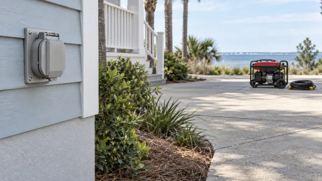
Use Chapter 10's install-now, enable, or defer review for future backup provisions. Before fixing the distribution layout, have a qualified backup-power designer identify any priority-circuit grouping, source-interface constraints, and equipment space or service access that today's work should preserve. Candidate locations must accommodate the contemplated source's ventilation, separation, and environmental needs. This consultation should resolve decisions that construction could foreclose, not become a premature sizing or transfer-equipment specification. Reserved space alone establishes neither compatibility nor an approved future installation.
Evaluate coastal exposure at the equipment location, not merely at the Santa Rosa Beach address. A conditioned utility room, damp garage, and exposed exterior wall may present substantially different conditions. Have the electrician assess direct rain, wind-driven moisture, condensation, salt deposition, existing corrosion, and manufacturer environmental limitations. Enclosure suitability for water exposure and resistance to corrosion are separate questions; a single rating or a claim of coastal durability may not establish both. Owners can identify visible rust, staining, or recurring dampness on accessible surfaces without opening equipment.
Compare locations by both the exposure they reduce and the constraints they introduce. An overhang may reduce rainfall without preventing salt deposition or condensation. Moving equipment indoors may improve protection but introduce heat-dissipation or service-access conflicts. An added cover is not an automatic remedy because it can obstruct ventilation or servicing. Compare manufacturer-supported enclosure and material choices, mounting conditions, and maintenance access rather than assuming the most sheltered-looking location is suitable.
Resolve water and site concerns before selecting a location. Relevant evidence includes known flooding or leaks, standing water, roof runoff, irrigation spray, drainage patterns, and available survey or elevation information. Qualified professionals should verify property-specific flood information and applicable equipment-location requirements, including how relevant elevations relate to the proposed equipment. Neither a coastal address nor apparently higher ground establishes an acceptable installation elevation. Where a location depends on drainage changes, structural support, or building alterations, the responsible licensed professionals must evaluate those dependencies.
Hypothetical example: a seasonally occupied home needs refrigeration and remote temperature reporting. Its continuity plan must address power for the refrigerator, sensor, router, and modem or optical network terminal, but household backup cannot prevent an internet-provider or monitoring-service outage. Cellular fallback adds a different communications path, yet still depends on coverage, network availability, and powered devices. The consequential choice is whether remote reporting is merely informative or triggers an intervention: define when a missed check-in prompts contact with a local caretaker, with visits only when access is safe. Locally stored temperature history may help evaluate conditions afterward but cannot deliver an alert while disconnected. Food or medication decisions after an uncertain interruption must follow applicable storage guidance; silence from the monitoring system is not evidence that conditions remained acceptable.
12. Coordinate Cable Routes, Access and Finish Restoration
A minimally disruptive installation is a conclusion to verify, not a starting promise. The electrician and renovation contractor should evaluate the complete path from distribution equipment to each destination, distinguishing accessible spaces from cavities merely suggested by drawings or room geometry. The homeowner can flag recently completed finishes, delicate surfaces, fixed furnishings and rooms where displacement would be difficult. Compare alternatives by expected openings, visible components, restoration boundaries and unresolved conditions, not cable length alone.
Transitions often determine whether a route works: between floors, additions, ceiling levels and cabinet runs. An accessible attic does not establish that the wall below it can be reached. A short path behind fitted cabinetry may require more demolition than a longer path through a utility area. The electrician should verify that the proposed wiring method suits the location and that connection points requiring access will remain accessible. Temporary construction openings and permanent service-access provisions should be identified separately.
Compare concealed routing, surface raceway and planned openings where each is feasible. Concealed routing through existing accessible spaces preserves appearance, but obstructions may leave the opening count uncertain. Surface raceway can reduce finish disturbance and provide a defined pathway for later professional work, although fittings, boxes and transitions may be more conspicuous than straight sections. Review samples where they would actually appear, including conflicts with trim, doors and furniture. Planned openings offer more predictable working access but add patching, drying and refinishing. A hybrid route may conceal wiring in prominent rooms while accepting visible raceway elsewhere.
Use the existing-condition assessment in Chapter 2 to target route-specific uncertainties: wall construction, blocking or bracing, plumbing and ducts, interrupted cavities and undocumented alterations. Where an answer could change the selected route, authorize limited professional investigation before accepting a concealment claim. Include restoration of exploratory openings even if the route is rejected. Suspected hazardous materials require specialist assessment before disturbance.
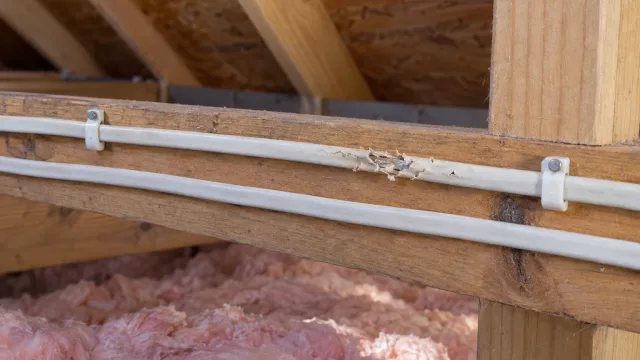
Routing must preserve the assemblies it crosses. Structural members cannot simply be altered to make a path convenient; proposed changes may need structural review. Coordinate wiring with insulation and identify disturbed air, water and vapor-control layers. In humid conditions, air leakage between conditioned rooms and an attic can create moisture problems that a cosmetic patch will not resolve. Penetrations through fire-resistance-rated assemblies and other required protective features need appropriate restoration, not generic filler. Assign these tasks to the appropriate licensed professionals rather than assuming they are included in electrical installation.
Access created by other renovation work is useful only when the electrical work can be completed before closure. Identify the particular walls, ceilings or cabinet areas that must remain open until required inspections and concealed-assembly restoration are complete. Confirm that insulation replacement will not obstruct required access. Chapter 14 covers the broader construction sequence; here, the key dependency is whether a route relies on an opening available only during a limited part of the renovation.
Finish expectations can change which route is preferable. Spot painting may leave a visible boundary even when the original paint formula is available, because existing color and sheen can change with age. Side lighting can expose texture differences. Wallpaper, tile, paneling and millwork may lack matching replacement materials, making a larger restoration area necessary. Before choosing the route, distinguish an acceptable localized repair from restoration of an entire wall, ceiling or continuous finish area. An alternative with fewer openings is not necessarily less disruptive if those openings affect finishes that are difficult to reproduce.
- Room clearing: Assign who empties cabinets, moves and returns furnishings, protects electronics and handles artwork or heavy pieces. Identify fixed millwork requiring professional removal and whether furniture must be moved more than once.
- Protection and cleanup: Specify floor and countertop protection, dust containment, protection of adjoining spaces, debris removal and cleaning. Account for how barriers and stored furnishings affect passage through the home.
- Hidden restoration: Identify responsibility for insulation, air and moisture-control layers, and required protection at penetrations. These tasks are separate from visible patching and painting.
- Finish repair: Define backing, replacement materials, texture, primer and paint coverage as applicable. Identify unavailable matching materials, sample approval responsibilities and who corrects work that does not meet the agreed appearance standard.
- Route comparison: For each viable alternative, show visible components, likely openings, permanent access needs, affected finishes and storage displacement. Mark unresolved conditions explicitly so a low-disruption preference is not mistaken for a verified installation plan.
13. Compare Complete Proposals and Confirm Approval Responsibilities
Send every bidder the same dated project baseline, incorporating the design decisions and restoration limits established in Chapters 1, 12. Require responses to identify equipment models or performance criteria, circuit counts and purposes, fixture and device quantities, control functions, and departures from that baseline. Separate product supply from installation and setup. Fewer circuits, owner-supplied fixtures or omitted finish repairs are scope differences, not evidence of a better price for equivalent work.
Compare proposals in a matrix with bidders as columns and work categories as rows. Mark each entry included, allowance, excluded or unresolved, and identify who handles excluded work. Check equipment ratings, compatibility, substitution conditions, availability and warranty-service responsibilities rather than brand names alone. Confirm that controls include necessary accessories and programming, restoration follows Chapter 12’s limits, and the price includes the professional calculations and Chapter 15 closeout deliverables specified for the project. A lump sum can be adequate if its supporting scope makes these obligations clear.
Use the consolidated owner-budget checklist below to capture costs beyond the electrical contract. Tag each entry as a contract commitment, allowance, outside quote or unresolved estimate, and record when payment is expected. Do not count allowances or owner purchases twice, and do not treat an unknown charge as zero. Keep contingency as an owner-controlled reserve for uncertainty, not permission to expand the work.
Require separate disclosures for assumptions, allowances, exclusions and unresolved conditions. An assumption should state what must prove true, who verifies it and which decision depends on it. An allowance should identify quantities, product and labor coverage, reconciliation method and markup on differences. An exclusion should name the party expected to arrange the work. For unresolved existing conditions, compare the cost of separately authorized professional investigation before commitment with the uncertainty of pricing installation now. If investigation must wait, require a pricing basis and authorization trigger; 'existing conditions extra' is not a useful boundary. Chapter 14 covers change authorization.
Verify the contracting entity and responsible professionals through official licensing records, matching names and authorized scope to the agreement. Obtain current insurance evidence and confirm coverage dates and applicable workers’ compensation arrangements with the insurer or agent. Ask for experience with comparable modernization work, not just finished-project photographs. References can help establish whether allowances were realistic, disruptions were coordinated and deficiencies were resolved. Identify subcontractors, who hires and pays them, and who remains accountable for electrical, access and restoration deliverables.
For the specific Santa Rosa Beach property, assign responsibility for confirming the applicable permitting authority and required approvals; the mailing address alone does not establish jurisdiction. Allocate document preparation, submissions, fees, review responses, inspection scheduling, deficiency correction and delivery of approval evidence. Assign correction costs according to their cause rather than treating every correction as an extra. Separately assign utility coordination, including confirmation of applications, equipment acceptance, interruptions and reconnection requirements. Identify necessary owner signatures and property-specific consents. Distinguish approvals needed before procurement or installation from later inspections, and recognize agency and utility scheduling as external dependencies.
Request itemized alternates showing the price adjustment and changes to functions, equipment, allowances, restoration and future work. For proposed phases, ask whether each endpoint is complete and usable, what dependencies remain, and whether later work repeats mobilization, finish removal, design or approval effort. Do not accept necessary assessment or required protection as optional deductions. Compare payment milestones with identifiable deliverables; clarify deposits, ownership of stored equipment, and how substitutions, offer expiration or delayed selections affect pricing. Before selection, resolve scope gaps, incorporate accepted alternates and establish precedence among conflicting proposal and contract documents. Choose on the comparable whole-project obligation, not the lowest initial total.
- Investigation and design: assessment, calculations, drawings and any separately authorized investigation; distinguish included services from later design charges.
- Approvals and utility costs: application and approval fees, utility-related charges and coordination services; identify which amounts remain unconfirmed.
- Equipment and installation: base contract, selected alternates, delivery and applicable taxes; show allowances within, not added again to, the contract total.
- Access and restoration: protection, access work, debris removal and the agreed finish-restoration scope, including any separately contracted work.
- Owner purchases: fixtures, appliances or controls outside the contract, plus delivery, storage and any installation charges excluded from the electrical proposal.
- Disruption and contingency: anticipated lodging or workspace costs when needed, plus a separate owner reserve reflecting unresolved conditions and pricing uncertainty.
- Ongoing obligations: optional subscriptions, manufacturer-directed maintenance and service outside warranty coverage; keep these distinct from construction spending.
14. Sequence Construction and Manage Changes in an Occupied Home
Build the construction schedule around release conditions, not dates alone. Each phase needs prerequisites, a defined work area, an interruption window and a condition for returning space to household use. Separate overall completion from occupancy milestones such as restoring refrigeration or reopening a hallway. Identify what controls each milestone: equipment availability, inspection, utility attendance or another trade’s completion. For seasonal occupancy, account for owner and guest arrival dates, but do not treat those dates as reasons to release unfinished work.
Resolve appliance selections under Chapter 6 before releasing affected circuit designs for construction. Complete the relevant design and obtain applicable approvals before the work they govern begins. Confirm critical replacement equipment is available before disabling existing equipment. Coordinate utility disconnection and reconnection with the electrician’s schedule; a crew booking alone does not establish restoration time. Rough-in must reach any required inspection stage before concealment. Cabinetry, restoration, finish devices and appliance connections then follow their actual dependencies. Energization depends on professional readiness checks and applicable inspection and utility conditions, not simply the scheduled finish date.
Issue outage notices early enough for occupants to arrange alternatives, then reconfirm when dependencies are settled. Each notice should identify affected rooms and equipment, whether the interruption is local or whole-home, expected start and duration, remaining uncertainty and the contact responsible for updates. Set a decision time for activating alternatives if restoration slips. Occupants may need off-site work arrangements, refrigerated-food storage or assistance with powered accessibility equipment. Coordinate refrigerated medicines with a pharmacist or medical provider, and powered medical equipment with the healthcare team and equipment supplier. A projected reconnection time is not a substitute for those arrangements.
The contractor should establish barriers, delivery and storage zones, crew access and separation between occupied areas and unfinished electrical work. Preserve usable routes to bedrooms, bathrooms and exits, including access for mobility devices. Agree on entry hours, key control, guest notification, pet containment and end-of-day security. At each daily handoff, identify released spaces, unavailable equipment and barriers that must remain. If the next day’s work removes a necessary route or household function, resolve the occupancy arrangement before starting it.
Include necessary temporary electrical service and lighting in the contractor’s scope. The licensed electrician should specify the source, supported loads, protective arrangements, equipment locations, applicable approvals, maintenance and removal. Evaluate this provision against actual household needs: lighting alone does not preserve refrigeration, cooling or accessibility equipment. Ask whether later cutovers interrupt the temporary supply, who responds after hours and what alternative applies if it becomes unavailable. Temporary equipment and routing must not obstruct exits or create cord hazards; occupants should not be left to supply disabled rooms through improvised extension-cord networks.
Use one change-order process for concealed conditions and owner-requested additions. Before affected extra work proceeds, obtain authorization from the designated owner representative, except for necessary immediate protective action. Making a condition safe does not authorize an unlimited redesign. Distinguish work necessary to complete the agreed scope safely from optional improvements, and identify unaffected work that can continue while the decision is pending.
Approve each phase for occupancy on its own merits. The occupied area needs complete, usable electrical systems serving it, necessary alarms, lighting and receptacles, safe exits, a usable bathroom, refrigeration, suitable temperature control and a workable food-preparation arrangement. Supporting non-electrical services must also remain available. Compare the burden of repeated temporary restoration with planned relocation, especially when successive cutovers would repeatedly disrupt essential routines. Set relocation triggers before construction: loss of accessible routes, an uncertain overnight interruption of necessary cooling or accessibility equipment, or any outage incompatible with the medical continuity plan.
- Change reason and scope: Record the location, discovered condition or requested addition, practical alternatives and resulting restoration work.
- Cost decision: State the price or agreed pricing basis and what it includes. Separate necessary corrective work from optional additions so approval is not bundled.
- Schedule decision: Identify effects on ordered equipment, design review, approvals, inspections, other trades and outage windows. State when a delayed decision begins affecting the schedule.
- Phase decision: Determine whether the change prevents the next space or system from being released. Compare proceeding now with deferral, including repeated access and restoration; revise the phase boundary or occupancy plan rather than skipping a required dependency.
15. Verify Performance Before Accepting the Finished Project
Completion has two distinct acceptance gates. Regulatory inspection addresses applicable requirements through the responsible authority’s process; the contractual walkthrough checks the delivered functions against approved room plans, final selections and authorized changes. Obtain the final inspection status and disposition of correction notices. Passing inspection does not settle a failed contractual function, and a successful walkthrough does not replace required approval.
Use the checklist below after professional startup, fixture installation and control programming are complete. Mark each applicable item pass, fail or deferred, identifying the room or equipment, verification date and supporting result. A deferred item needs a reason, responsible party and scheduled review; it is not a pass. Missing appliances, unfinished work or unsuitable viewing conditions may prevent meaningful verification.
The electrician performs electrical testing and equipment verification; homeowners participate through normal operation of completed appliances, lights and controls after readiness is confirmed. Do not open electrical equipment, conduct live testing or deliberately reproduce a fault. Demonstrations should establish the agreed functions, not create an improvised maximum-load challenge.
- Approval status , Confirm that required inspection results are available and correction notices have been resolved or explicitly remain open. Identify any outstanding approval separately from contractual performance defects so neither is obscured by a general statement that the project is complete.
- Professional verification , Review records identifying the circuits or equipment checked, date, qualified person, applicable procedure, results and limitations. The electrician should verify circuit-directory accuracy, protective-device operation using applicable manufacturer procedures, and suitability of installed equipment ratings and combinations. Compatibility checks must cover final fixture, driver and control models, including substitutions. Include relevant startup results from other licensed trades; an inspection approval alone is not a substitute for these records.
- Room-plan functions , Operate finished appliances, switches and controls normally and compare their responses with the approved plans. Confirm switch assignments, visible receptacle locations and practical access with cabinetry and planned furnishings accounted for. An appliance that operates demonstrates that function, not wiring correctness or spare capacity. Record deviations from the approved plan as defects; treat newly requested features as proposed changes.
- Lighting and controls , Demonstrate the acceptance criteria established in Chapters 7, 8: approved zones, task visibility, glare expectations, dimming behavior, named scenes and manual overrides. Check agreed dimming limits for flicker, dropout or unexpected switching. Have the contractor demonstrate promised offline functions under the specified conditions; internet loss and hub unavailability are different tests. Protect essential services during demonstrations. Defer lighting judgments that require different daylight conditions rather than marking them satisfactory without observation.
- Punch-list resolution , For each failure, record the exact location and device, approved requirement, starting conditions, expected response and observed response. Assign the correction and target date, then specify the retest needed for closure. If a scene operates the wrong zone even though every fixture illuminates, the control requirement remains failed. After correction, repeat the original sequence and check affected neighboring functions. Have the responsible professional identify any restriction on use. A remedy that removes an agreed function requires acceptance as a scope change, not closure as a successful repair.
- Closeout package , Reconcile the existing project records with the finished installation: updated circuit directories and panel schedules; as-built equipment locations and known routing, with unknown routes labeled; final model details and manuals; control schedules; inspection, approval, test and commissioning records; and warranties with applicable start dates, registration responsibilities and service contacts. Superseded selections should not be presented as installed equipment.
- Acceptance decision , List every unresolved defect, deferred demonstration and missing document with its responsible party, due date and required closure evidence. Identify what has passed and what remains outside acceptance under the contract’s closeout provisions. Do not erase open obligations merely because equipment is energized or the walkthrough has ended.
16. Maintain the Modernization and Hand It Off Clearly
Assign ongoing responsibility for receiving occupant reports, arranging service, authorizing changes and maintaining the electrical record. In a managed property, define what the manager may authorize when the owner is unavailable and name an alternate contact. Keep unfinished contractor obligations distinct from maintenance needs arising after acceptance so each reaches the appropriate responsible party.
Build the maintenance plan from manufacturer instructions and a licensed electrician’s assessment of the installed equipment and its actual exposure, not a universal inspection interval. Each entry should identify the equipment, required professional service, due date or condition-based trigger, and responsible contact. Ask whether observed humidity, salt exposure, water exposure or demanding operation warrants different attention. A coastal address alone does not establish equipment condition. Manufacturer notices, storm damage or changed status indicators may require review before a scheduled visit. For seasonal occupancy, assign someone to notice and report accessible changes between stays; remote monitoring cannot establish that equipment remains sound.
During ordinary use, occupants should promptly report new buzzing or crackling, unusual odors, discoloration, visible corrosion, damaged controls, intermittent operation or changed equipment status indicators. Use the symptom-recording approach in Chapter 2: note where and when the change occurred, what was operating and any preceding outage or storm, without recreating the event. Stop using suspect equipment pending professional advice. Smoke, sparking or a strong burning odor takes priority over documentation: keep people away and seek emergency help. Stay clear of water-exposed electrical equipment.
Have the electrician explain the installed equipment’s accessible status indicators and the appropriate reporting response, particularly for surge protection and load management. Distinguish a utility outage from an equipment warning in the contact instructions, without asking occupants to diagnose either. The person managing the property should acknowledge reports, communicate any restrictions on use and track professional follow-up. A cleared app notification or a symptom that stops is not, by itself, a reason to close a report.
Maintain the Chapter 15 closeout package as the property’s continuing electrical record rather than creating a second archive. Add service findings and subsequent alterations, including replacement model details and revised operating restrictions. Preserve the project-specific capacity assumptions and future provisions established in Chapters 3 and 10: what was reserved, for which anticipated equipment, what remains deferred and which compatibility constraints apply. These conclusions, not a general label such as “future-ready”, help the next electrician understand the design intent. After changes, obtain updates to affected records and mark superseded versions. Keep the record accessible to the owner and authorized professionals independently of any departing contractor or manager.
Prepare a separate, short operating sheet for household members, tenants and guests. Describe normal wall controls, intentional schedules, ordinary overrides and the demonstrated functions available without internet access. Include the property contact, alternate, electrical service contact, utility outage-reporting contact and emergency reporting expectations. Explain which changes to report and how to report them; do not assign panel access, troubleshooting or breaker resets. At each handoff, confirm that the sheet matches the current controls and is available without an owner-account login. Keep administrative credentials and technical records separate from guest instructions.
Before ordering a later major appliance or adding equipment, have a licensed electrician compare its requirements with the current installation and retained design assumptions. An ownership change is also a useful point to identify undocumented alterations and proposed new uses. Previously reserved provisions may depend on a particular equipment rating, compatible control system or load-management arrangement; they are not approval for every replacement. If new loads are deferred, retain the functioning existing arrangement and its restrictions rather than altering settings or deleting accounts in anticipation of an unreviewed upgrade.
- Before smart-control turnover: identify the account owner, administrators, delegated users, hubs, subscriptions, connected services and recovery methods. Determine whether any operational function depends on the outgoing account.
- During transfer: follow the manufacturer’s ownership-transfer procedure. Where supported, establish owner-controlled administration and individual, limited permissions for managers or tenants instead of sharing the owner’s password. Coordinate any transfer affecting load-management operation with the electrician.
- Before closing access: verify the incoming administrator’s access and recovery options, then revoke departing users and obsolete integrations. Review schedules, remote permissions, billing and retained occupancy information.
- Protect continuity and privacy: transfer recovery credentials securely outside the general property record. Avoid an indiscriminate factory reset, which may erase needed configurations. Confirm normal control operation after the transfer and resolve discrepancies before considering the handoff complete.
About this guide: This resource provides general homeowner education, not a remote diagnosis. Actual conditions, code requirements, equipment, and safe repair options must be evaluated at the property.